 |
Toshiba Satellite P740, P740D, P745, P745D disassembly.
|
|
|
 |
STEP 1
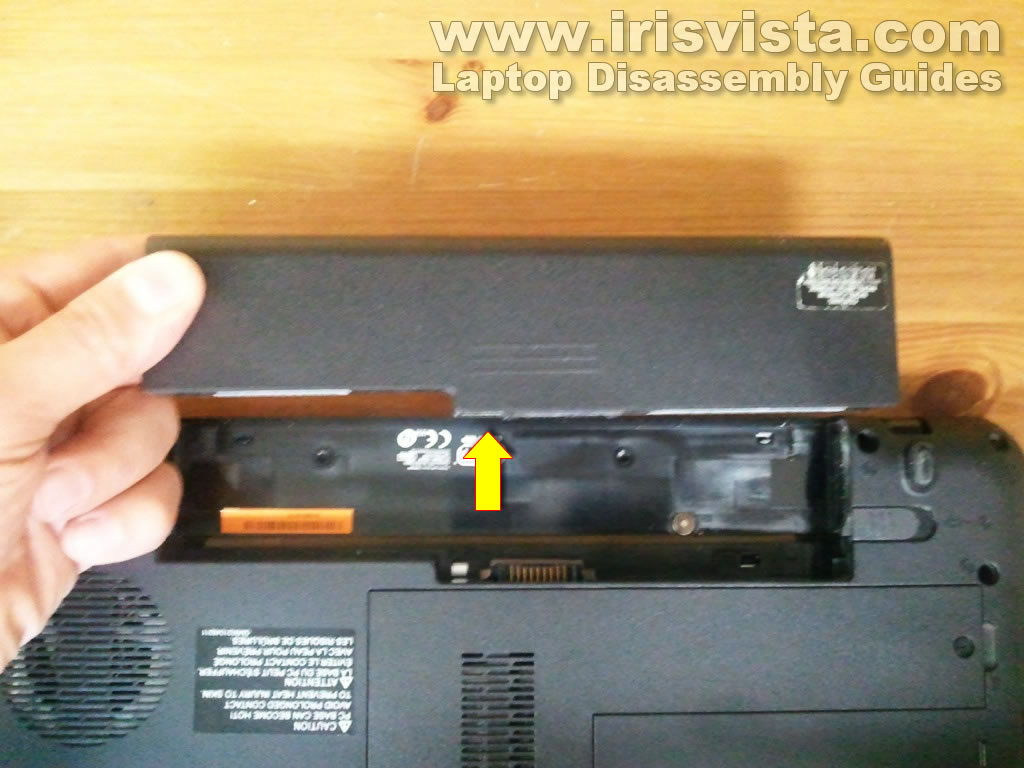
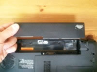
Make sure the laptop is turned off.
Unlock and remove the battery.
|
| |
|
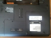 |
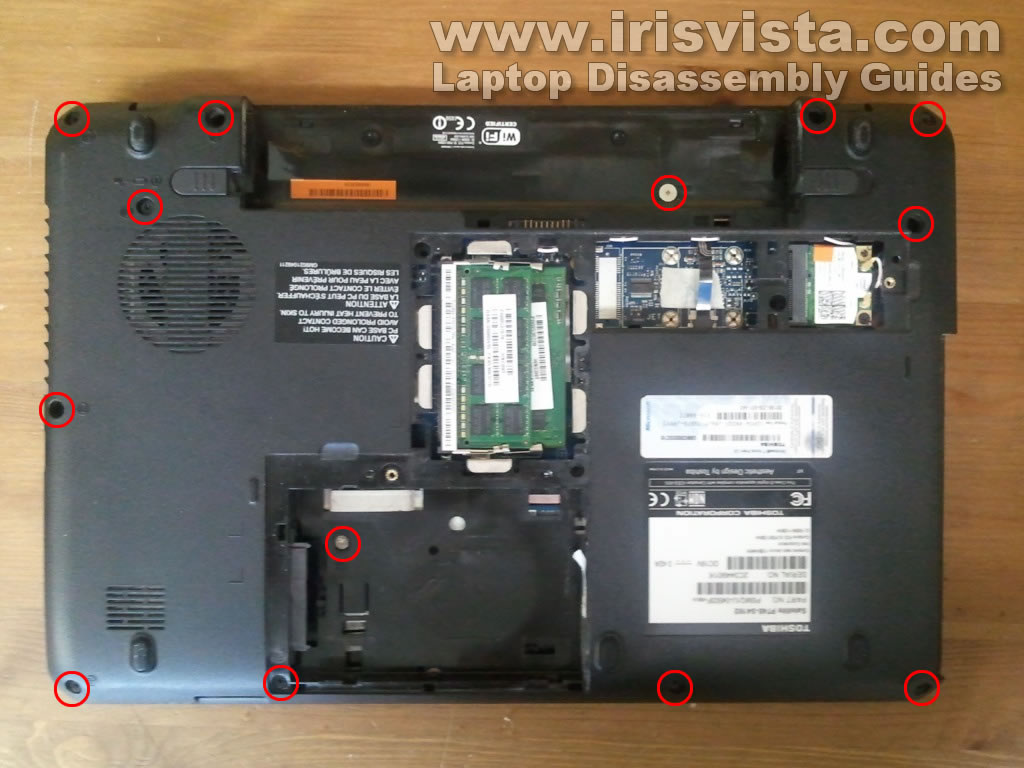
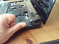
STEP 2
There are two covers located on the bottom of the laptop: the hard drive cover and memory cover.
Remove two screws securing these covers.
Remove both covers.
|
| |
|
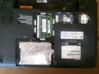 |
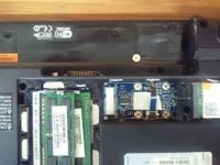
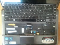
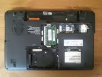
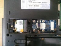
STEP 3
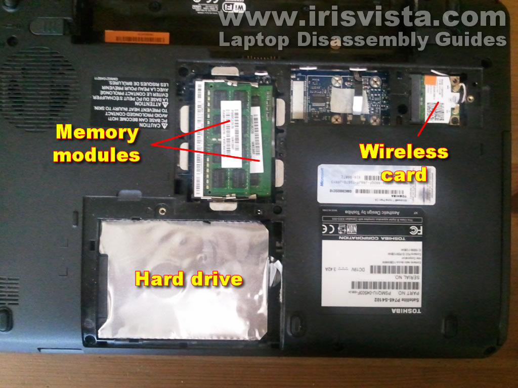
On the bottom of the laptop you can get access to the hard drive, both memory modules and wireless card.
For now I will leave both memory modules and wireless card connected to the motherboard. |
| |
|
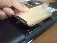 |
STEP 4
In order to disconnect the hard drive from the motherboard you'll have to slide it to the right.
After that you can lift up and remove the hard drive from the laptop.
Toshiba Satellite P740/P740D/P745/P745D use regular 2.5" SATA hard drive. |
| |
|
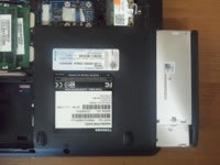 |
STEP 5
Remove one screw securing the DVD drive on the bottom of the laptop.
Pull the DVD drive from the laptop and remove it. |
| |
|
 |
STEP 6
Remove two screws securing the keyboard. |
| |
|
 |
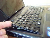
STEP 7
In the battery compartment you'll find a small plastic latch securing the keyboard.
Push on the latch with a small screwdriver.
When you push on the latch , the keyboard will lift up a little bit and you'll be able to insert your fingers under the keyboard as it shown in on the next picture. |
| |
|
 |
STEP 8
Insert your fingers under the keyboard and start separating it from the laptop. |
| |
|
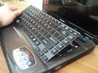 |
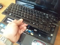
STEP 9
Continue removing the keyboard. |
| |
|
 |
STEP 10
Be careful, the keyboard still connected to the motherboard.
The keyboard connector located under the keyboard.
Before you can pull the cable from the connector you'll have to unlock the connector as it shown in the following two steps. |
| |
|
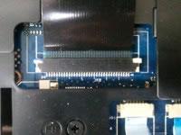 |
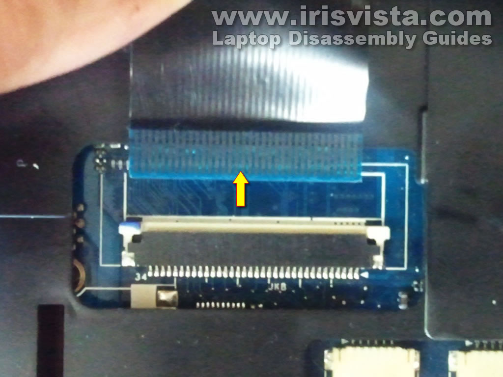
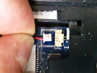
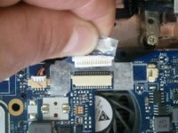
STEP 11
Carefully slide the white retainer about 1-2 millimeter towards the screen.
The retainer MUST remain attached to the connector base. |
| |
|
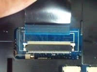 |
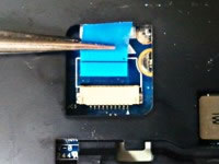
STEP 12
On this picture you can see the same connector in the UNLOCKED state.
You see, the white retainer still attached to the connector.
Now you can pull the keyboard cable from the connector. |
| |
|
 |
STEP 13
Remove the keyboard from the laptop. |
| |
|
 |
STEP 14
Remove all screws from the bottom of the laptop. |
| |
|
 |
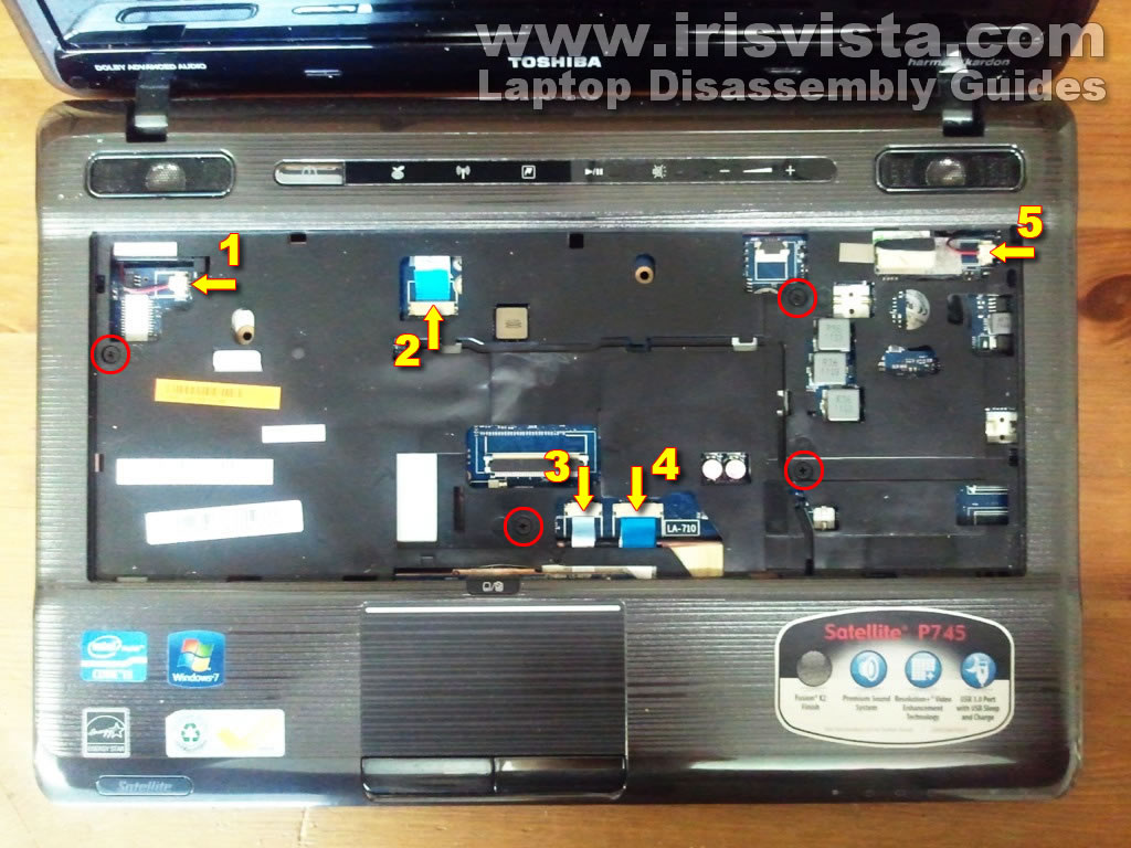
STEP 15
Remove four screws securing the top cover assembly.
Disconnect the following cables:
1. Left speaker cable.
2. Media control board cable.
3. Touchpad cable.
4. Touchpad button board cable.
5. Right speaker cable.
I explain how to disconnect all cables in the following steps.
|
| |
|
 |
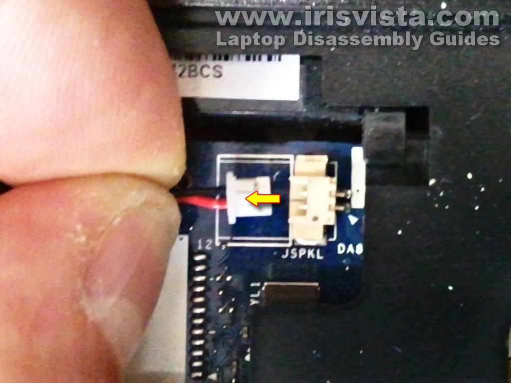
STEP 16
Carefully unplug the left and right speaker cables from the connector on the motherboard.
Do not pull by the wires. |
| |
|
 |
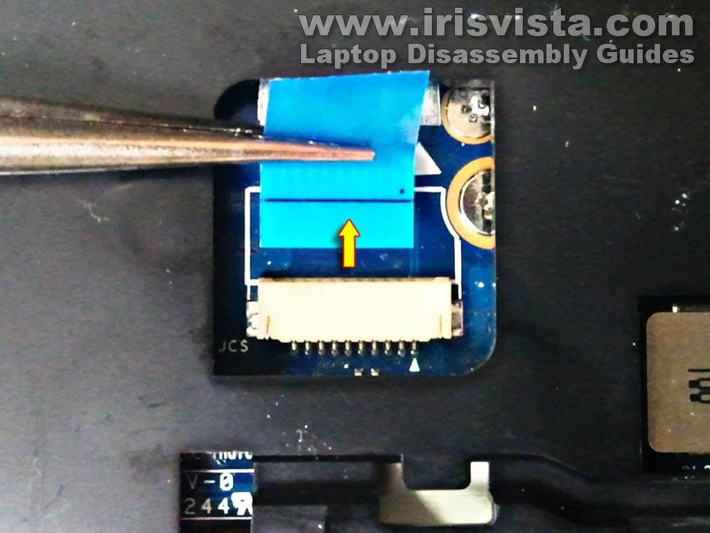
STEP 17
The touchpad and media control board connectors do not have retainers.
Simply pull the cable from the connector. There is nothing to unlock. |
| |
|
 |
STEP 18
Start separating the top cover/palmrest assembly from the laptop base.
|
| |
|
 |
STEP 19
Remove the top cover/palmrest assembly. |
| |
|
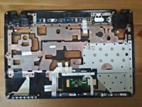 |
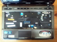
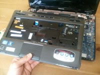
STEP 20
On this picture you can see the bottom part of the top cover/palmrest assembly.
On this side you can access both speakers, the media control board, touchpad and touchpad button board. |
| |
|
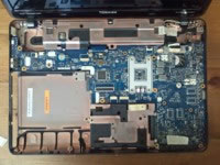 |
STEP 21
The top cover removed from the laptop. Now you can get access to the motherboard.
By the way, the CMOS battery is soldered to the motherboard. |
| |
|
 |
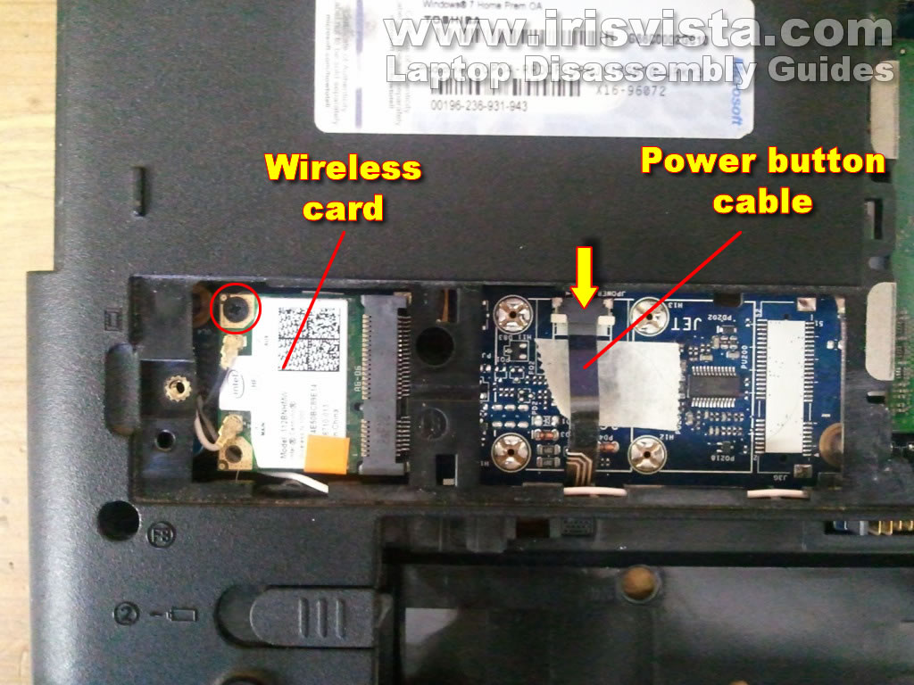
STEP 22
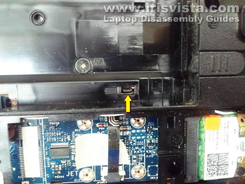
In order to remove the motherboard you'll have to disconnect the power button cable and pull the wireless card.
Disconnect the power button cable using same technique as for disconnecting the keyboard cable.
Remove one screw securing the wireless card. |
| |
|
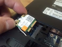 |
STEP 23
I didn't disconnect wireless card antennas.
I just pulled the wireless card from the slot with the antennas attached.
Turn the laptop over but don't forget you still have the wireless card hanging on the bottom. |
| |
|
 |
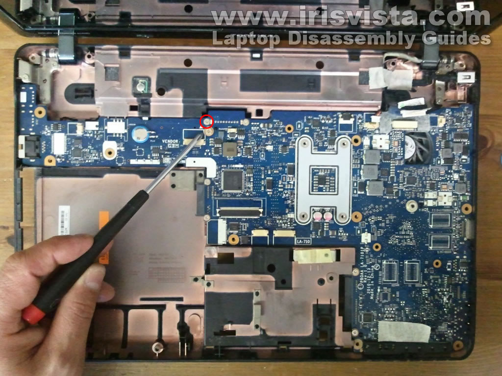
STEP 24
Remove one screw securing the motherboard. |
| |
|
 |
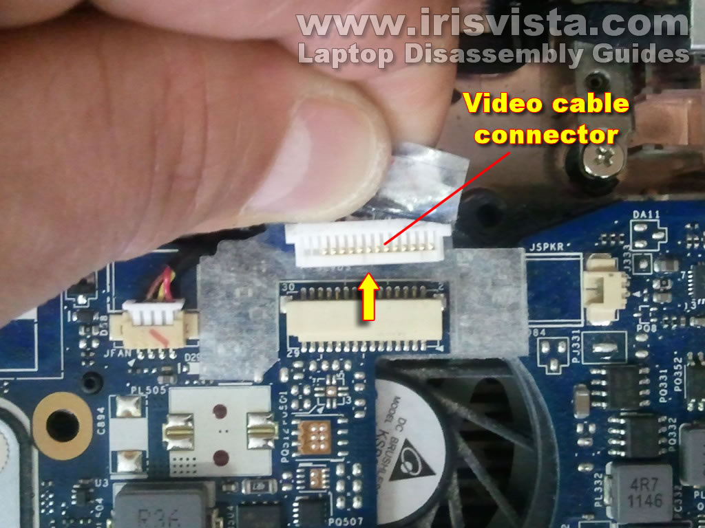
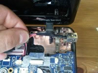
STEP 25
Unplug the video cable connector from the motherboard. |
| |
|
 |
STEP 26
Unroute the DC jack harness. |
| |
|
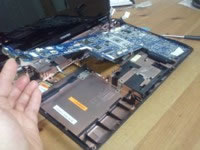 |
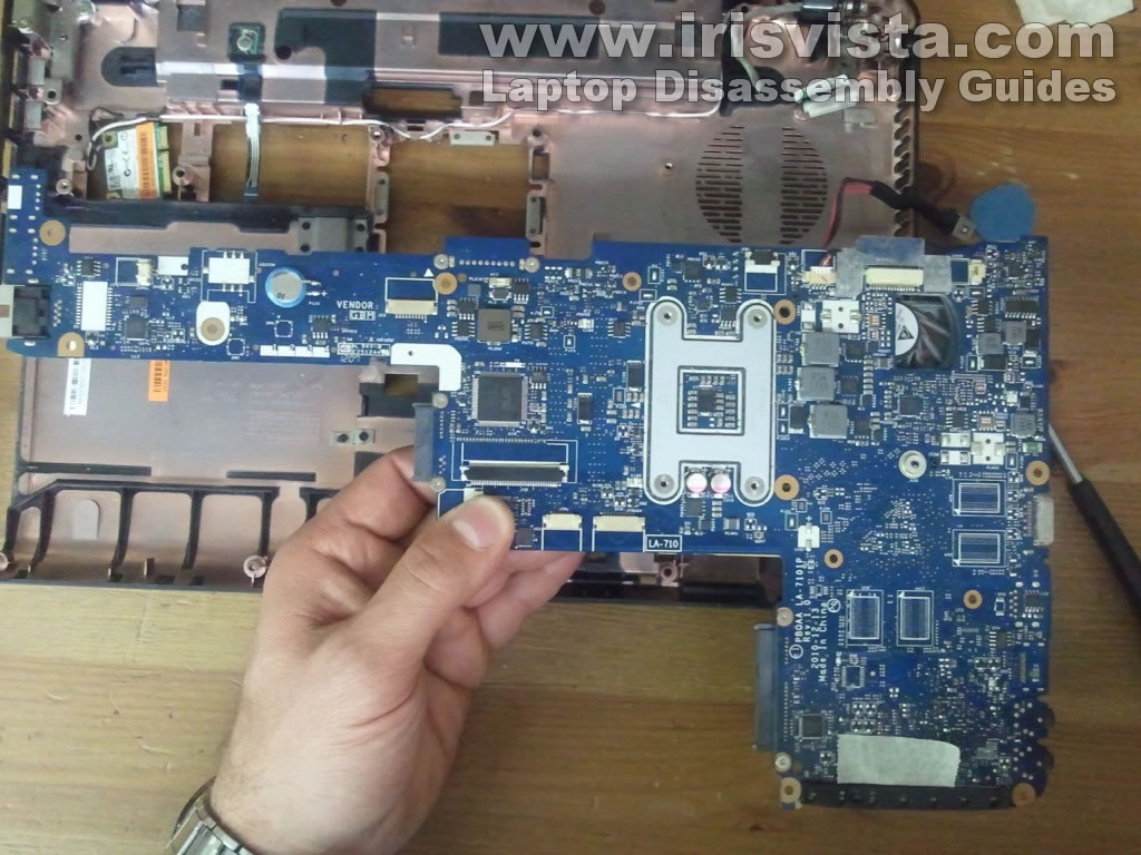
STEP 27
Now you can start removing the motherboard from the laptop. |
| |
|
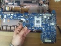 |
STEP 28
The motherboard removed. |
| |
|
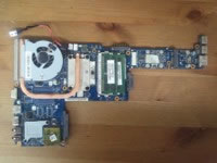 |
STEP 29
Here's the bottom side of the motherboard. |
| |
|
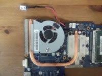 |
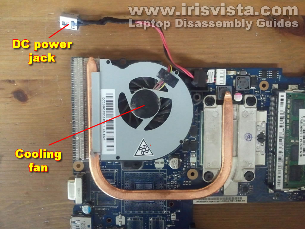
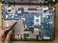
STEP 30
Here you can get access to the cooling fan for cleaning or replacement.
The DC jack is attached to the harness but the harness is soldered to the motherboard.
Take a look at this guide for screen removal. |
| |
|
|
|