 |
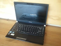
Toshiba Portege R835 R830 disassembly.
In the following guide I will show how to remove the laptop bottom cover and access main internal components. |
|
|
 |
STEP 1
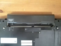
Make sure the laptop is turned off.
Open the battery lock (green arrow). Push the release latch to the right (yellow arrow) and remove the battery from the case.
|
| |
|
 |
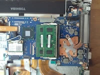
STEP 2
Loosen two screws securing the RAM cover.
Lift up and remove the cover.
Under the cover you will find both RAM modules.
|
| |
|
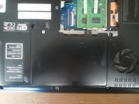 |
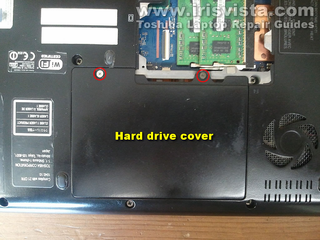
STEP 3
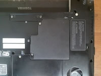
Loosen two screws securing the hard drive cover.
Lift up and remove the cover. |
| |
|
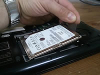 |
STEP 4
There are no screws securing the hard drive.
Lift up the back side of the drive by the attached tab. |
| |
|
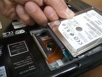 |
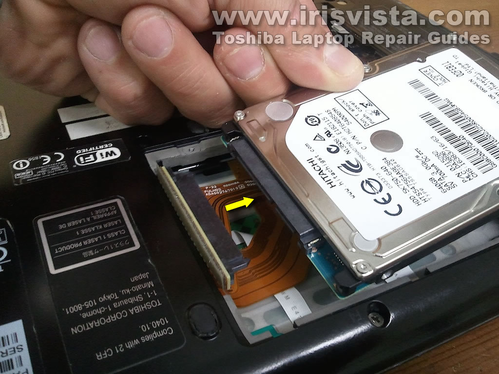
STEP 5
Carefully disconnect the SATA cable from the hard drive.
Remove the drive and replace it with a new one if necessary. |
| |
|
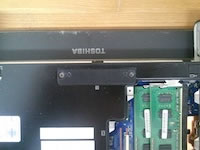 |
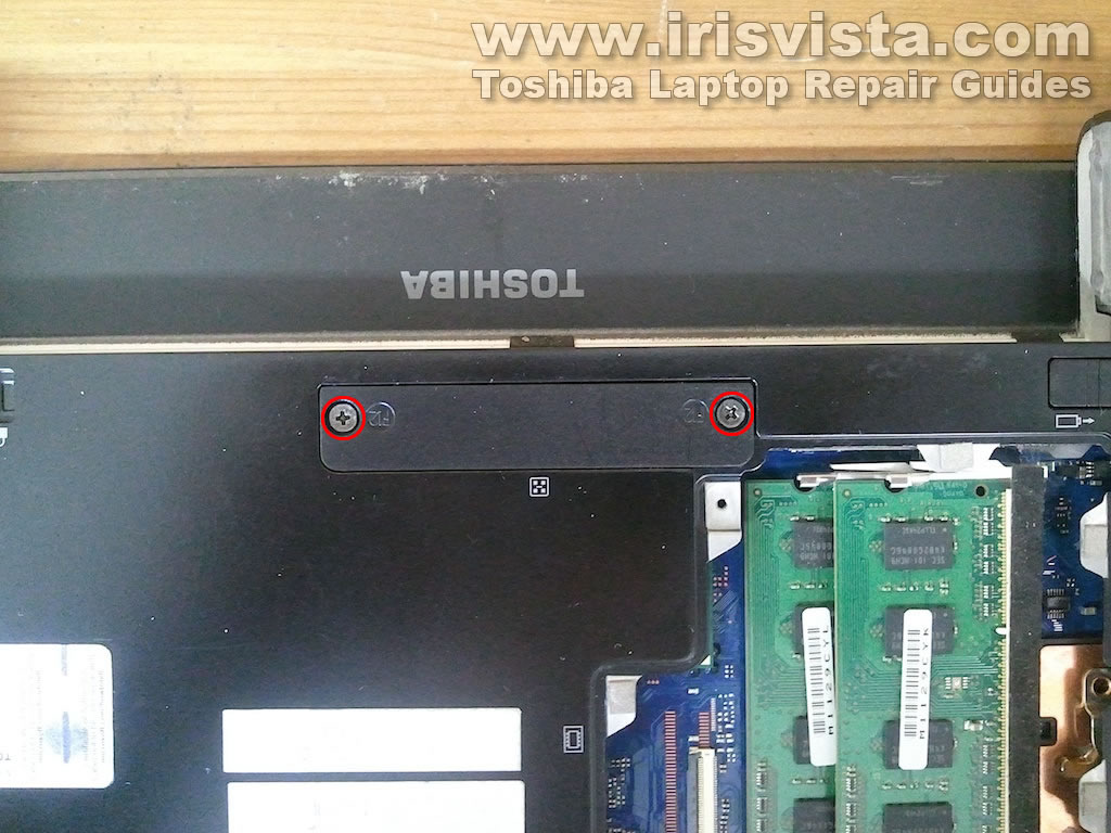
STEP 6
There is one more cover located under the battery bay.
Loosen two screws securing the cover and remove it from the case. |
| |
|
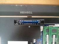 |
STEP 7
I think that's where the docking station connector should be located but it wasn't installed in my Portege R835.
Apparently, not all models have this docking connector by default. |
| |
|
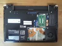 |
STEP 8
Remove all shown screws from the bottom.
By the way, the screw marked with a green circle also secures the optical drive. |
| |
|
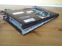 |
STEP 9
Separate the bottom cover from the case and remove it. |
| |
|
 |
STEP 10
Now you can access and remove the optical drive. |
| |
|
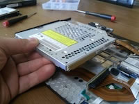 |
STEP 11
Carefully lift up the optical drive from the case.
Remove two screws securing the SATA cable to the drive. |
| |
|
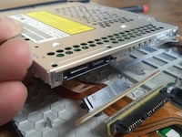 |
STEP 12
Unplug the cable from the drive.
Remove the optical drive completely.
|
| |
|
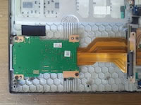 |
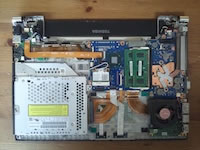
STEP 13
The card reader is located on a separate board.
It can be easily removed and replaced. |
| |
|
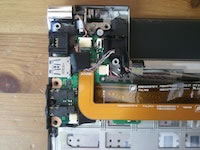 |
STEP 14
The audio jacks located on a separate board. |
| |
|
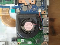 |
STEP 15
The cooling fan secured by two screws.
Remove two screws and unplug the fan cable from the motherboard. |
| |
|
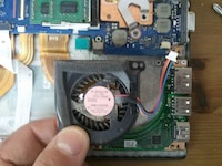 |
STEP 16
Now you can remove the fan for cleaning or replacement if necessary. |
| |
|
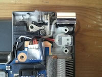 |
STEP 17
In Portege R835/R830 laptop the power connector attached to a cable.
If the connector failed, you can unplug it from the motherboard and replace with a new one. |
| |
|
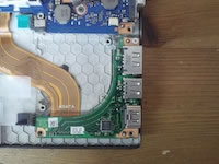 |
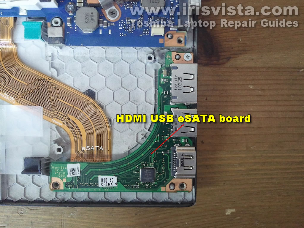
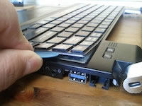
STEP 18
The HDMI and eSATA connector also located on a separate board. |
| |
|
 |
STEP 19
The wireless card slot located on the motherboard.
In order to remove the wireless card you'll have to disconnect two antenna cables, remove one screw securing the card and pull the card from the slot.
|
| |
|
 |
STEP 20
The keyboard is glued to the top cover with adhesive tape.
It's very easy to damage the keyboard while removing it, so do it only if necessary.
Here's another guide explaining how to remove the screen. |
| |
|
|
|