|
How to disassemble Toshiba Qosmio F40 F45. |
|
|
 |
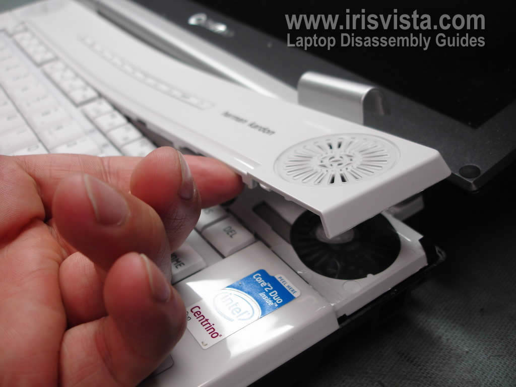
STEP 1
First of all, turn off the laptop, unplug the AC adapter and remove the battery.
In the following 6 steps I will be removing the keyboard.
Insert a piece of plastic (I'm using a guitar pick) between the button board cover and laptop base and carefully lift up one side of the cover.
|
| |
|
 |
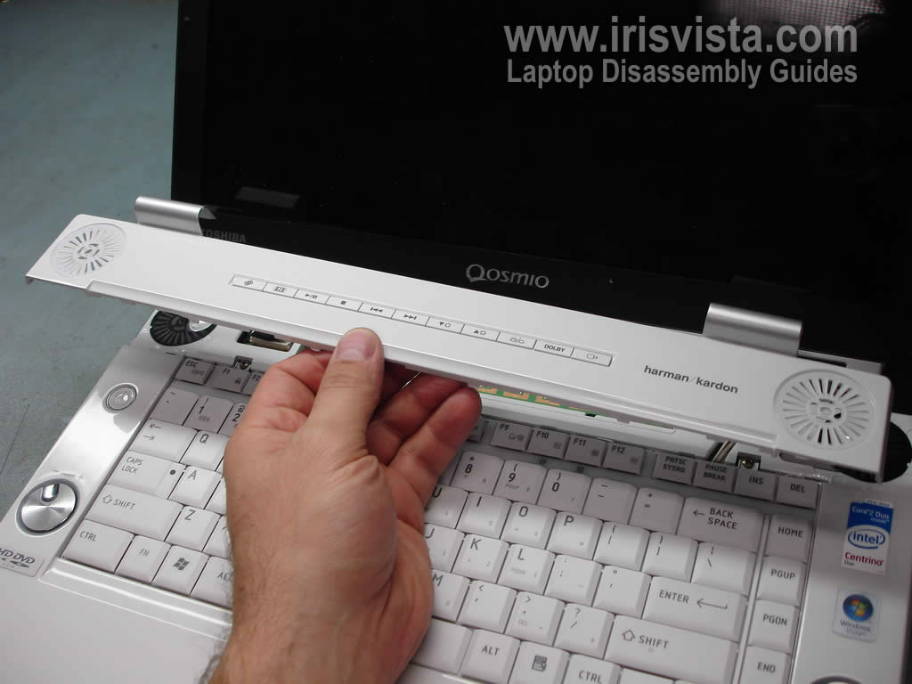
STEP 2
Continue removing the button board cover using fingers. You'll have to wiggle the cover a little bit to release a few hidden latches securing the cover.
|
| |
|
 |
STEP 3
The button board cover removed. |
| |
|
 |
STEP 4
Remove two screws securing the keyboard and lift up the keyboard from the base.
Work slowly, the keyboard is attached to the motherboard. |
| |
|
 |
STEP 5
Please the keyboards so you can access the cable connector underneath. |
| |
|
 |
STEP 6
You'll have to unlock the cable connector and release the cable before removing the keyboard.
Unlock the connector by moving the brown piece towards the display panel. Do not separate the brown piece from the white base.
WARNING! If you accidentally break the connector you'll have to replace the whole motherboard.
On this picture you see the connector in the unlocked position. |
| |
|
 |
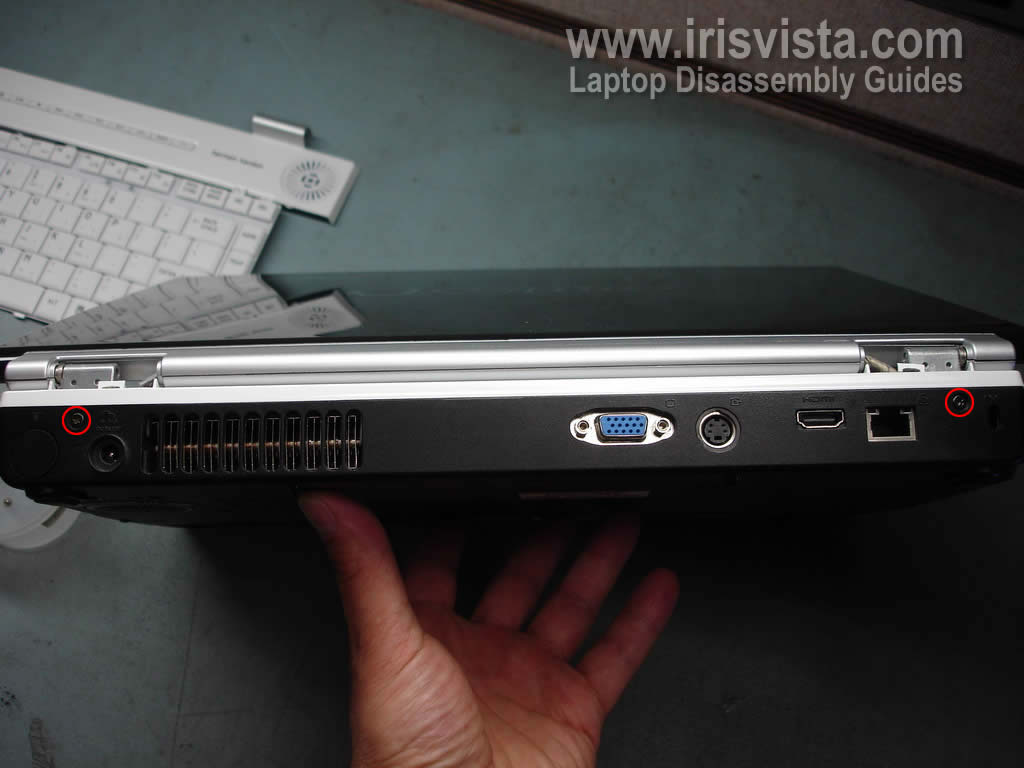
STEP 7
In the following three steps I'll be removing the display panel.
Remove two screws securing display hinges on the back of the laptop. |
| |
|
 |
STEP 8
Remove four screws securing display hinges (two screws per hinge).
Disconnect the video cable from the motherboard.
Disconnect three wireless card antenna cables from the wireless card.
Disconnect two remaining cables from the motherboard.
|
| |
|
 |
STEP 9
Lift up and remove the display panel assembly.
The LCD screen removal steps will be very similar to many other Toshiba laptops. Read through a few different guides and you'll get the idea. |
| |
|
 |
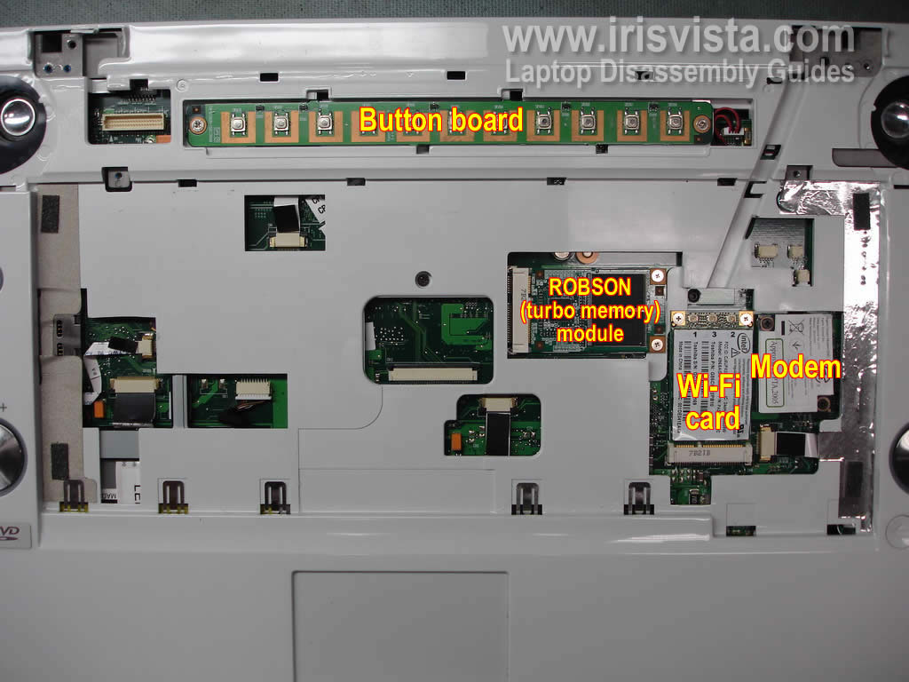
STEP 10
Some key components are located right under the keyboard and button board cover.
From here you can access and remove the button board, ROBSON module (turbo memory), wireless card and modem module. |
| |
|
 |
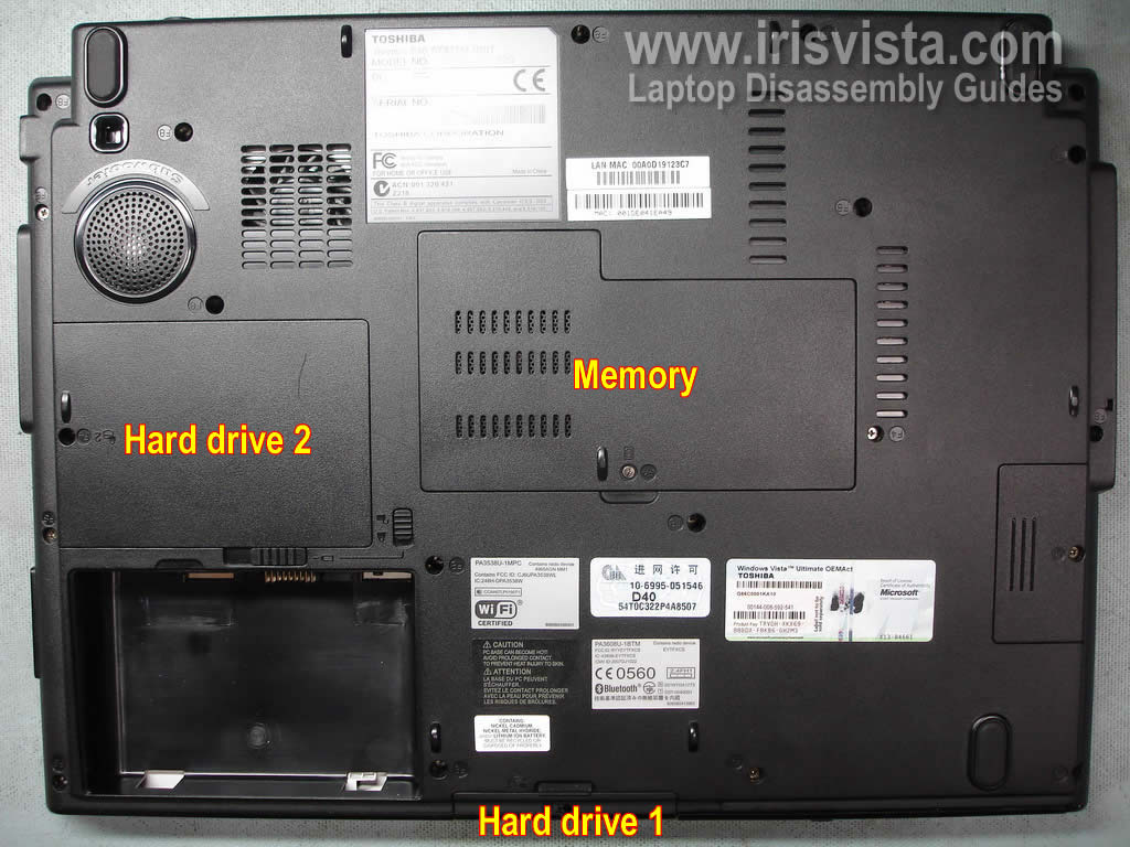
STEP 11
In the following 8 steps I explain how to open the laptop case and remove the top cover.
Remove hard drive 1, hard drive 2 and memory (RAM) covers from the bottom of the laptop.
|
| |
|
 |
STEP 12
Remove both hard drives.
Remove both memory (RAM) modules. |
| |
|
 |
STEP 13
Remove two screws securing the CD/DVD drive and push the drive from the laptop.
If you are replacing just the CD/DVD drive, you don't have to go through all previous steps. |
| |
|
 |
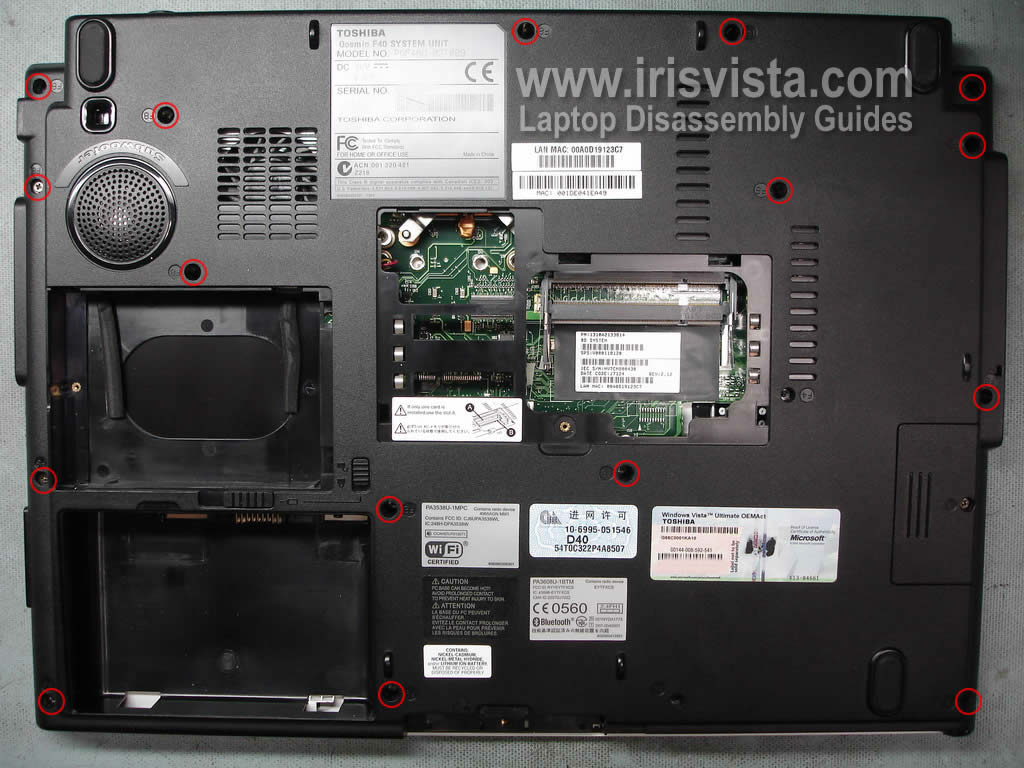
STEP 14
Remove all screws from the laptop bottom. |
| |
|
 |
STEP 15
Disconnect all cables and remove one screw securing the top cover. |
| |
|
 |
STEP 16
The top cover has gray tape glued to the card reader.
Unglue the tape before removing the top cover. |
| |
|
 |
STEP 17
Now you should be able to separate the top cover from the laptop base. |
| |
|
 |
STEP 18
Remove the top cover assembly.
|
| |
|
 |
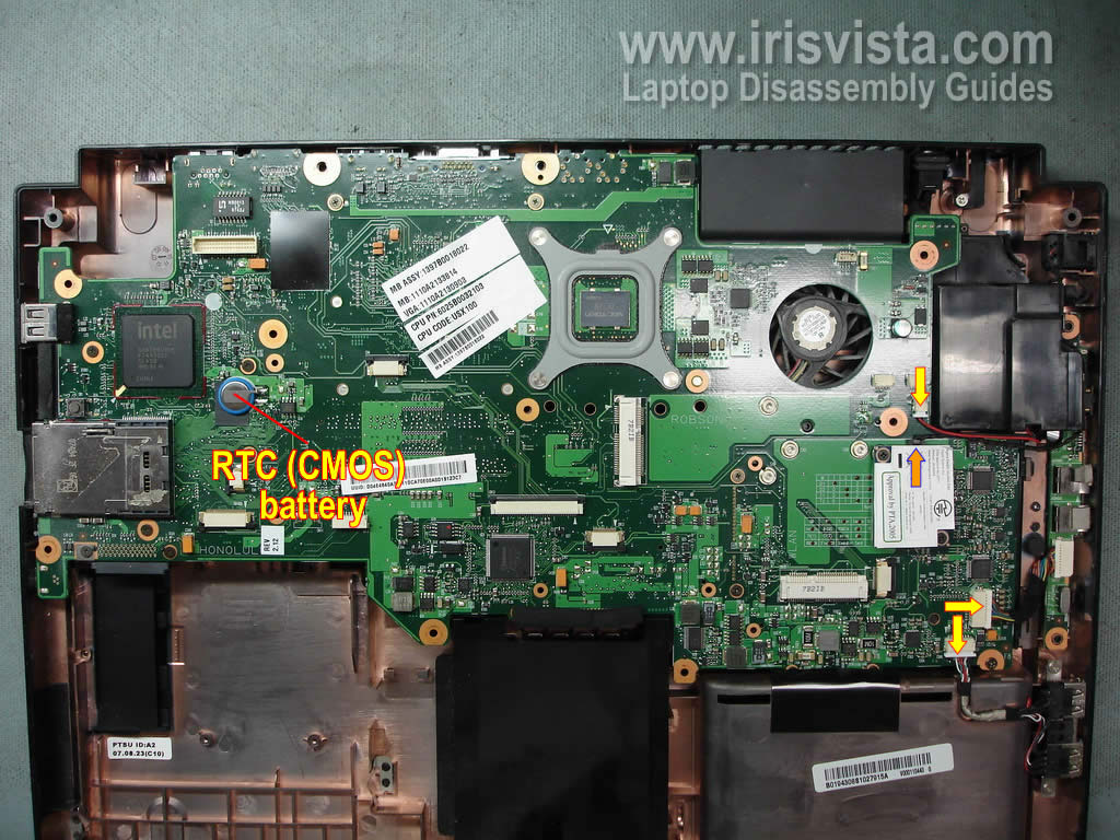
STEP 19
In the following 4 steps I remove the motherboard.
Disconnect three cables (yellow arrows) from the motherboard.
Disconnect one cable (orange arrow) from the dial-up modem module.
As you can see the CMOS (RTC) battery can be access from this side of the motherboard. The battery is soldered to the motherboard. By the way, removing or replacing the battery will not clear the BIOS password. |
| |
|
 |
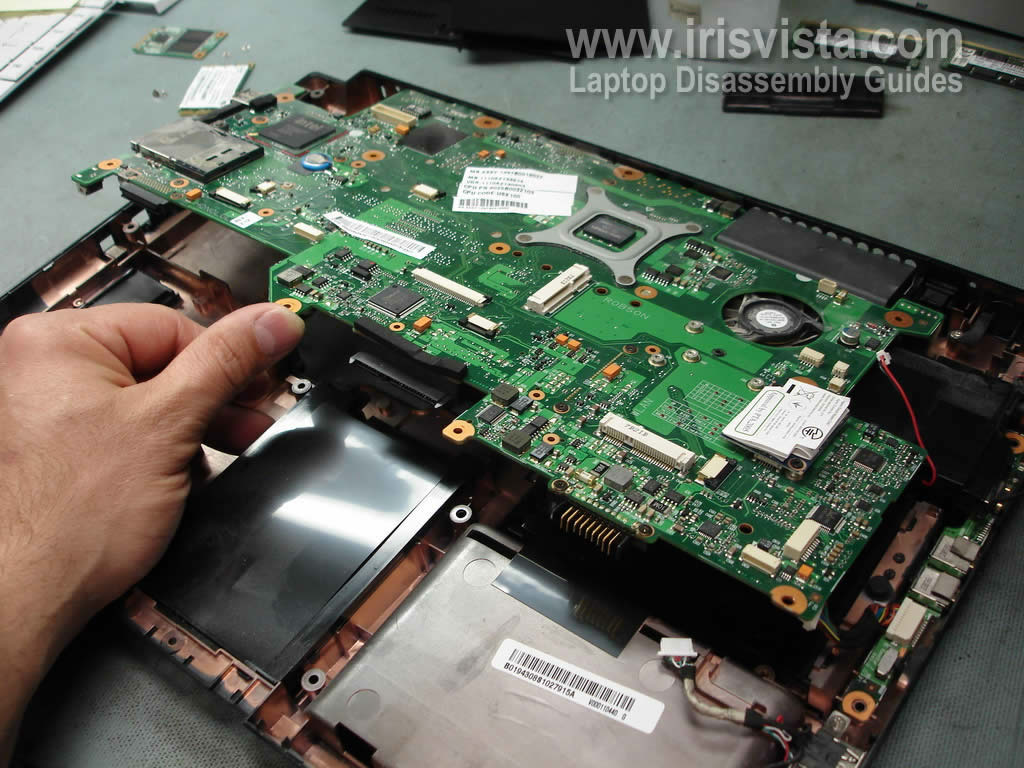
STEP 20
Lift up one side of the motherboard. |
| |
|
 |
STEP 21
Remove motherboard from the laptop base. |
| |
|
 |
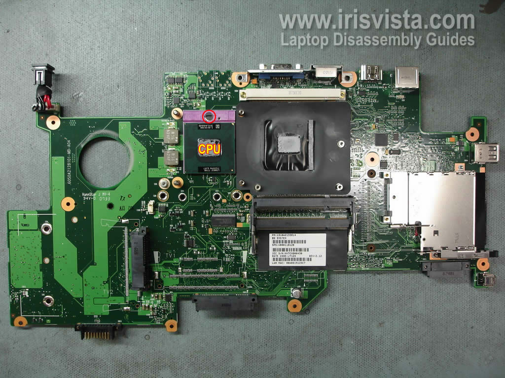
STEP 22
The motherboard has been removed.
|
| |
|
 |
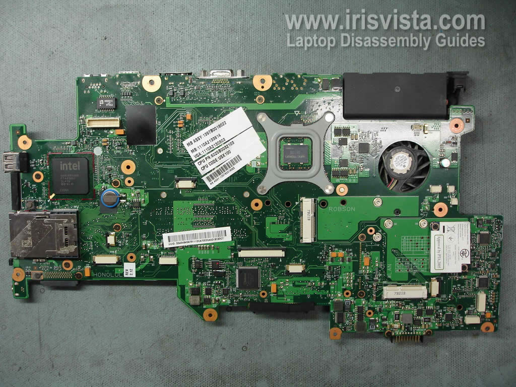
STEP 23
Here's the other side of the motherboard. |
| |
|
 |
STEP 24
Remove one screw from the metal bracket securing the video board heat sink.
Remove the bracket. |
| |
|
 |
STEP 25
Remove the video board heat sink. |
| |
|
 |
STEP 26
Remove two screws securing the video board to the motherboard. |
| |
|
 |
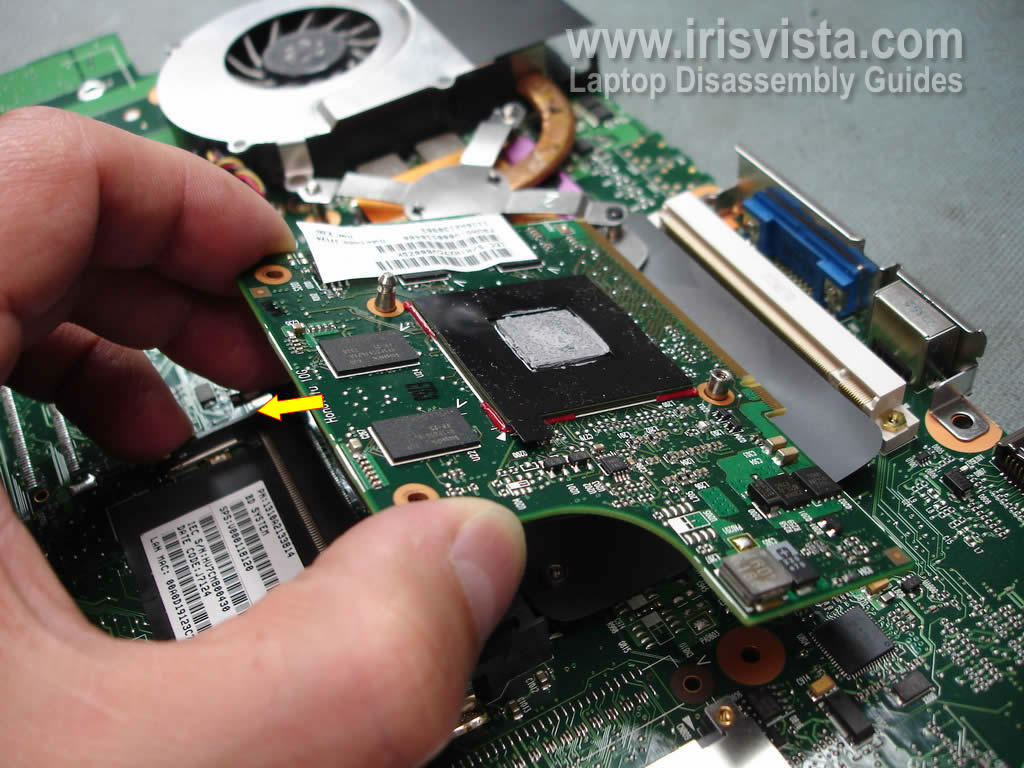
STEP 27
Pull the video board from the connector. |
| |
|
 |
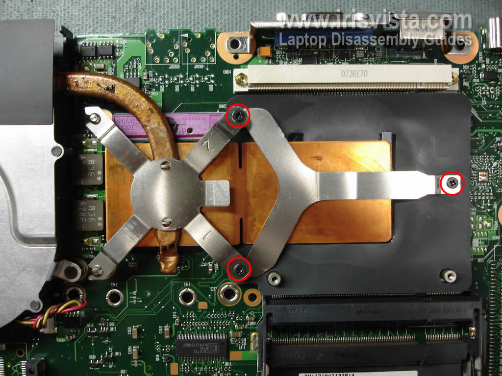
STEP 28
Remove three screws from the brackets securing the CPU heat sink. |
| |
|
 |
STEP 29
Remove the CPU heat sink.
In my laptop the heat sink was clogged with dust and needed a good cleaning.
|
| |
|
 |
STEP 30
Remove one screw securing the cooling fan.
Unplug the fan cable from the motherboard. |
| |
|
 |
STEP 31
Remove the cooling fan. |
| |
|
 |
STEP 32
Unlock the CPU socket by turning the screw into the "OPEN" positing.
Carefully remove the CPU.
You can see the power jack in the top left corner. The power jack is connected to the motherboard via cables. The power jack can be unplugged and replaced with a new one without soldering. |
| |
|
 |
STEP 33
Just in case I made a picture from the bottom side of the top cover. |
| |
|
|
|