|
Toshiba Qosmio G45 or G40 disassembly. |
|
|
 |
STEP 1
Turn off the laptop and remove the battery.
We'll start laptop disassembly with removing the keyboard.
Lift up the keyboard bezel with a sharp object, you can use a small flat head screwdriver.
|
| |
|
 |
STEP 2
Under the keyboard bezel you'll find two screws securing the keyboard.
Remove both screws securing the keyboard.
|
| |
|
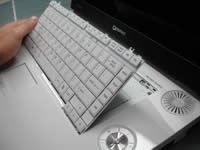 |
STEP 3
Press on the small plastic latch above the F8 key and release the keyboard.
Lift up the keyboard and place it upside down on the palm rest. |
| |
|
 |
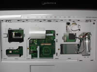
STEP 4
Remove the connector cover.
|
| |
|
 |
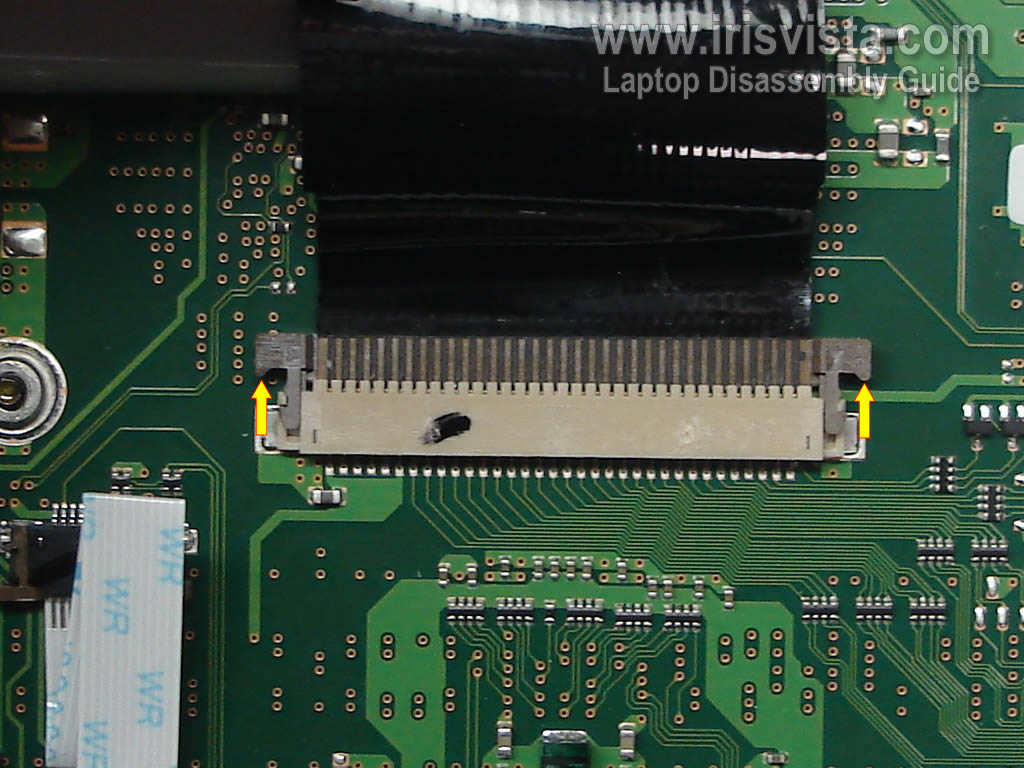
STEP 5
Now you can access the keyboard connector.
You have to unlock the connector and release the cable before removing the keyboard.
|
| |
|
 |
STEP 6
In order to unlock the connector, move the brown clip about 2 millimeters towards the LCD screen.
Do not separate the brown clip from the white connector base. The clip must stay attached.
If you break the connector, you'll have to replace the motherboard!
|
| |
|
 |
STEP 7
Remove the keyboard and replace it with a new one if needed.
|
| |
|
 |
STEP 8
Remove covers 1 and 2.
Remove one screw securing the top cover assembly.
|
| |
|
 |
STEP 9
Removing the wireless card:
Disconnect three wireless card antenna cables. Remove two screws securing the wireless card. Remove card from the slot.
Removing the modem card.
Remove two screws securing the modem card. Lift up the modem card to disconnect it from the motherboard (there is a connector underneath the card). Unplug the black cable from the right side of card.
Disconnect the brown antenna cable from the Bluetooth card. |
| |
|
 |
STEP 10
Lift up the Bluetooth module.
Disconnect the Bluetooth cable from the connector on the motherboard.
Remove the Bluetooth module and cable from the laptop. |
| |
|
 |
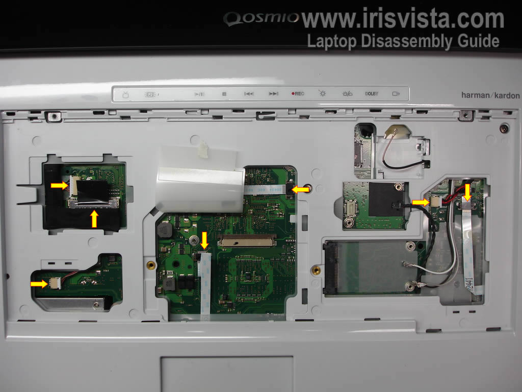
STEP 11
Disconnect all cable pointed with arrows. |
| |
|
 |
STEP 12
Remove two screws securing hinge covers.
|
| |
|
 |
STEP 13
Remove both hinge covers. |
| |
|
 |
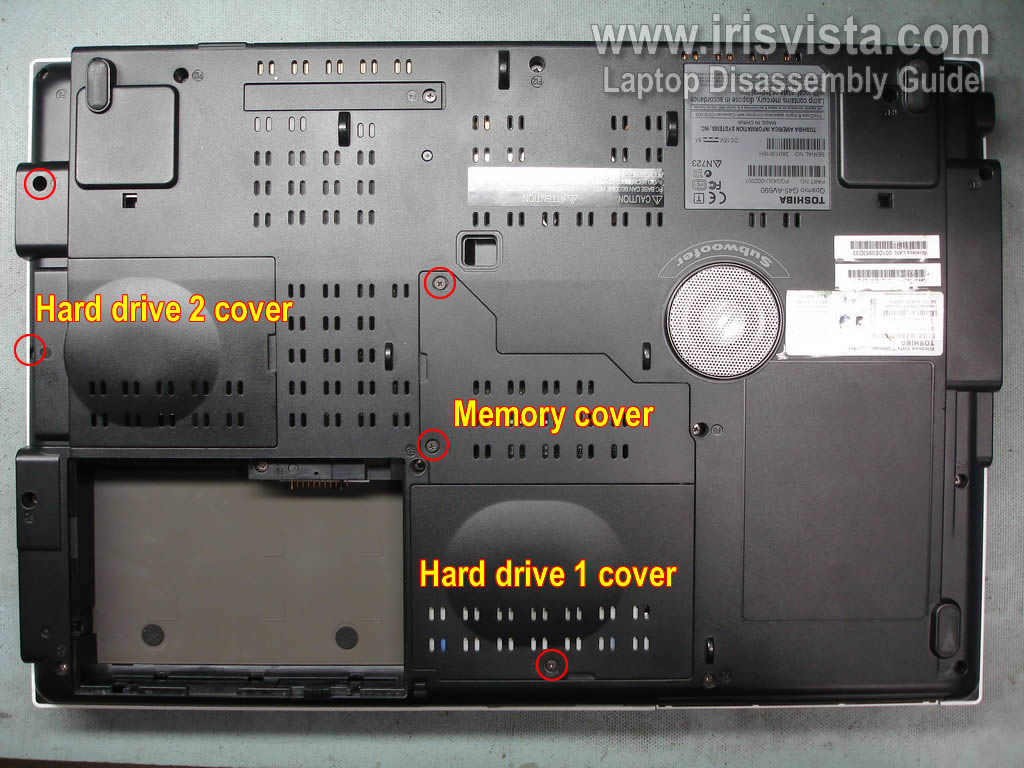
STEP 14
Remove the hard drive 1 cover.
Remove the hard drive 2 cover.
Remove the memory cover. |
| |
|
 |
STEP 15
I have only one hard drive installed in my laptop.
Lift up the hard drive and disconnect it from the cable.
Remove both memory modules. |
| |
|
 |
STEP 16
Remove all screws from the bottom of the laptop. |
| |
|
 |
STEP 17
Disconnect all cables pointed with arrows.
Also, you can disconnect the hard drive cable from the motherboard now or you can do it later. |
| |
|
 |
STEP 18
Start removing the bottom cover from the left side. |
| |
|
 |
STEP 19
Normally, the speaker has to stay attached to the bottom cover when you remove the cover.
In my case the speaker got separated from the cover.
You have to remove both, the bottom cover and speaker. |
| |
|
 |
STEP 20
Remove the bottom cover.
|
| |
|
 |
STEP 21
Here's the opposite side of the bottom cover.
You can see how speakers are connected to the bottom cover. |
| |
|
 |
STEP 22
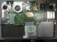
Here's the laptop without bottom cover. In the following steps I'll be removing the motherboard. |
| |
|
 |
STEP 23
Remove one screw securing the CD/DVD drive.
Disconnect the drive cable from the motherboard. |
| |
|
 |
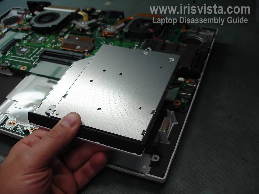
STEP 24
Remove CD/DVD drive from the laptop.
|
| |
|
 |
STEP 25
Remove one screw securing the DC jack cover to the laptop.
Disconnect the DC jack cable from the motherboard.
Remove the cover and jack together. |
| |
|
 |
STEP 26
Disconnect three cables pointed with yellow arrows.
Also, on this picture you can see where the CMOS battery is located.
Here's the tricky part.
There is one more cable which is hard to disconnect - the LED board cable. I pointed to this cable with a green arrow. I've been working on this Toshiba model for the very first time and completely overlooked the LED board cable. I just removed the motherboard without disconnecting the cable. When I assembled everything back together, I noticed that lights on the front of the laptop not working. I had to take it apart again to connect the cable. |
| |
|
 |
STEP 27
Do not disconnect the LED board cable from the motherboard, disconnect it from the LED board instead.
When you remove the motherboard, this cable will be attached to it. |
| |
|
 |
STEP 28
It's better to leave the LED board cable attached to the motherboard because the connector is located on the bottom part of the motherboard and it's hard to access it. |
| |
|
 |
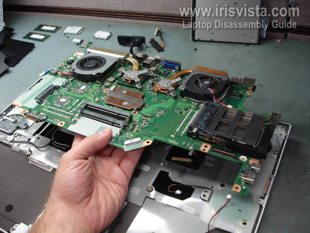
STEP 29
Remove the motherboard.
As you see, the LED board cable is not attached to the motherboard in my case because I overlooked it. |
| |
|
 |
STEP 30
Here's the top cover assembly without motherboard. |
| |
|
 |
STEP 31
Disconnect the CPU cooling fan cable from the motherboard.
Remove two screws securing the CPU cooling fan. |
| |
|
 |
STEP 32
Remove the CPU fan. |
| |
|
 |
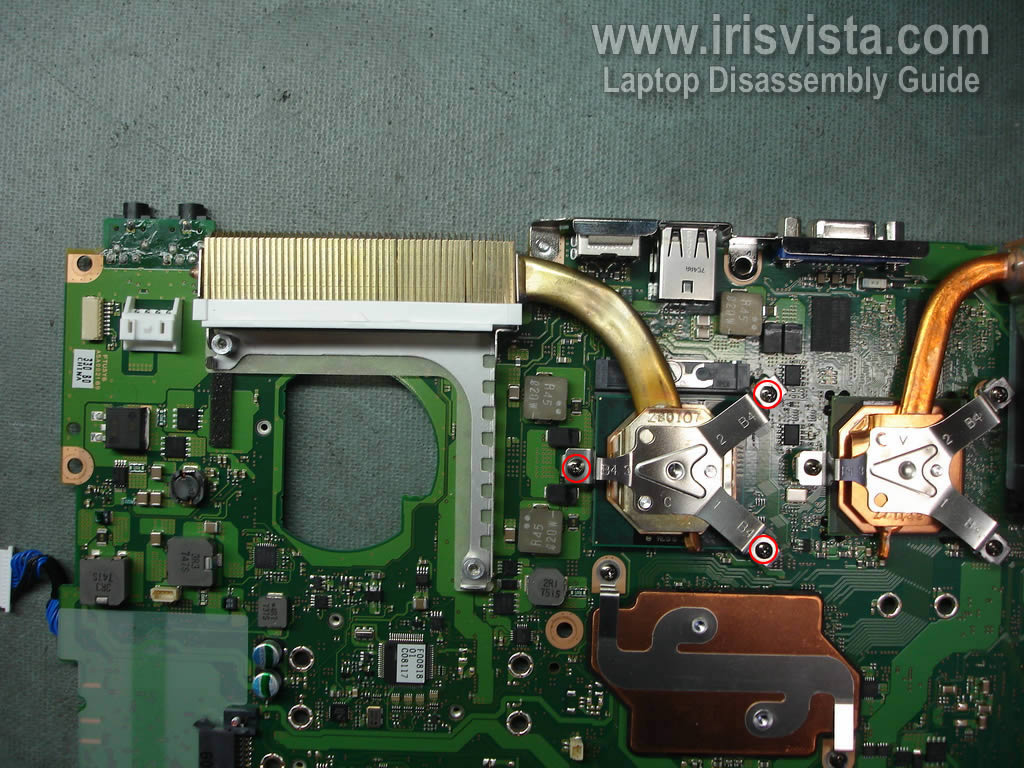
STEP 33
Remove three screws securing the heat sink bracket and remove the bracket.
|
| |
|
 |
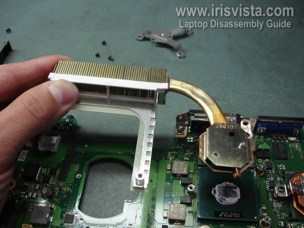
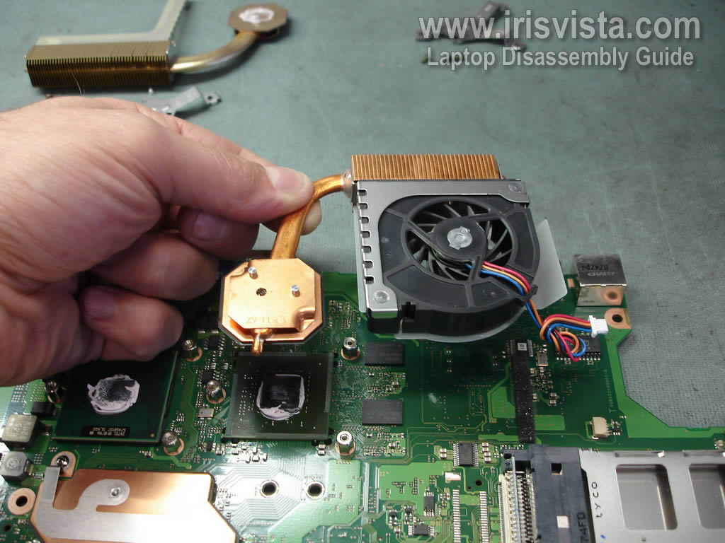
STEP 34
Remove the CPU heat sink. |
| |
|
 |
STEP 35
Disconnect the secondary fan cable from the motherboard.
Remove three screws securing the heat sink bracket. |
| |
|
 |
STEP 36
Remove the fan assembly. |
| |
|
 |
STEP 37
Disconnect one cable from the right side of the motherboard.
Unlock the CPU socket and remove the CPU.
Now you can replace the motherboard with a new one if needed. |
| |
|
|
|