 |
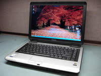
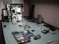
Toshiba Satellite M105, M100, Tecra A6 disassembly.
|
|
|
 |
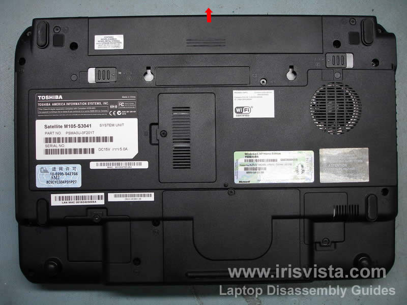
STEP 1
Unlock and remove the notebook battery.
|
| |
|
 |
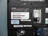
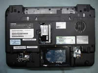
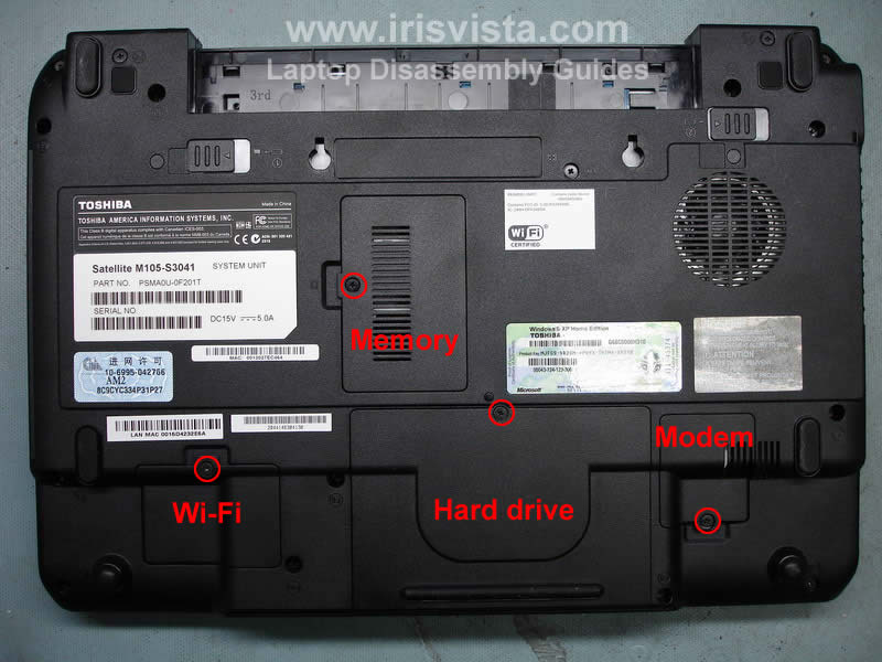
STEP 2
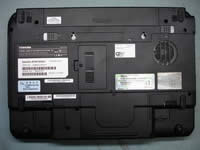
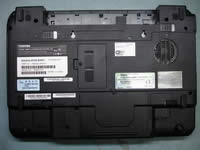
At this step remove all covers from the bottom of the notebook.
Wi-Fi card cover, memory cover, hard drive cover and modem card cover.
|
| |
|
 |
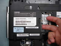
STEP 3
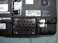
To remove the hard drive, slide it to the right until it's disconnected from the motherboard. Then lift it up.
The modem is secured by two screws. Remove the screws and carefully lift it up by the black tape. After you disconnect the modem from the connector on the motherboard, disconnect the modem cable (pointed with red arrow).
|
| |
|
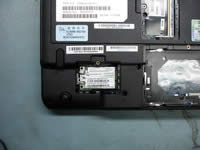 |
STEP 4
The wireless card in this model smaller then a regular wireless card.
To remove the wi-fi card, you have to disconnect the wireless card antennas. The connector is marked with a red circle. Grab one connector with your fingers and pull it up (It might be tight). Disconnect the second antenna cable too. After both cables are disconnected, remove the wireless card.
Use the same technique as for removing the memory module. Spread latches (shown with red arrows) and remove the wireless card. |
| |
|
 |
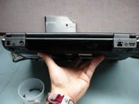
STEP 5
This screw secures the DVD drive inside the case. Remove the screw. |
| |
|
 |
STEP 6
In the memory bay you'll see a DVD bracket. Push on the bracket with a finger and slide the DVD drive out of the notebook base. Remove the drive. |
| |
|
 |
STEP 7
Remove all screws circled with a red arrow from the bottom of the notebook. |
| |
|
 |
STEP 8
At this step you'll have to remove two screws from the back of the notebook. These screws secure display hinges. In order to remove the display assembly, you'll have to remove these screws first. |
| |
|
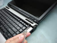 |
STEP 9
To remove the keyboard bezel use a small flat-head screwdriver or an awl. Insert the screwdriver between the keyboard bezel and the notebook base and gently pry it up. |
| |
|
 |
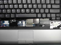
STEP 10
Lift up and remove the keyboard bezel. |
| |
|
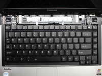 |
STEP 11
Remove two screws securing the keyboard. Gently press on the keyboard lock (red arrow) and lift up the keyboard from the base.
|
| |
|
 |
STEP 12
Place the keyboard so you can access the cable connector on the motherboard. Before you remove the cable, you have to unlock the connector. Using a small flat-head screwdriver or your finger nails open the lock. BE VERY CAREFUL WITH THE CONNECTOR!
After it's unlocked you can pull the cable and remove the keyboard.
|
| |
|
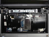 |
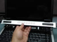
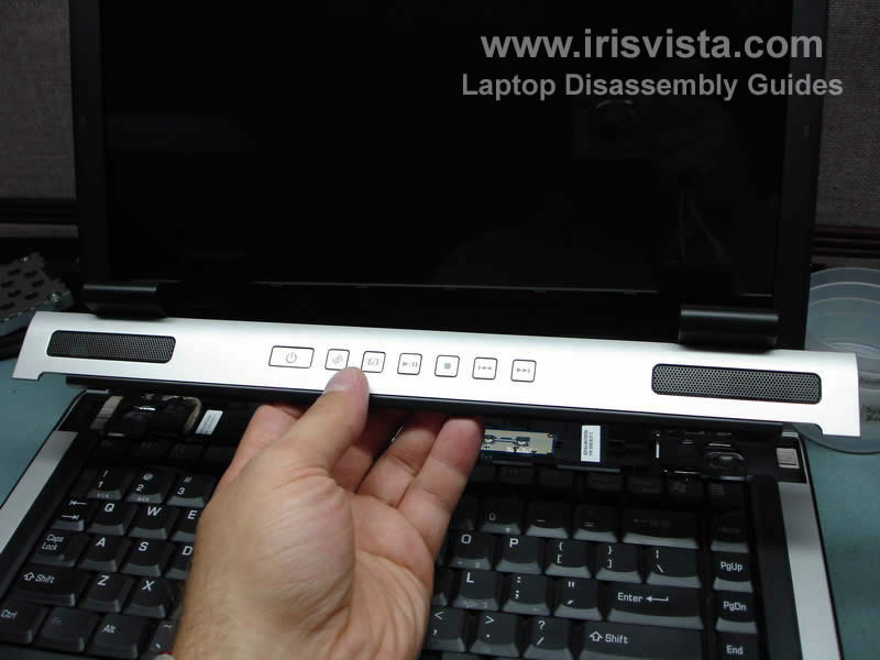
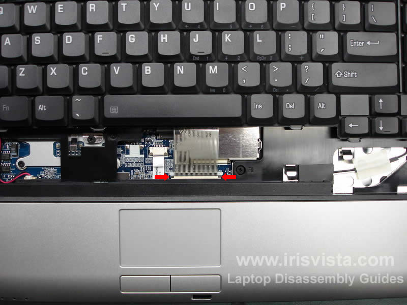
STEP 13
Remove the switch board in the following order:
- unlock the cable connector on the motherboard and pull the cable (red arrow)
- press on the lock located on the right side from the switch board and at the same time slide the board to the left
- lift up and remove the switch board |
| |
|
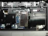 |
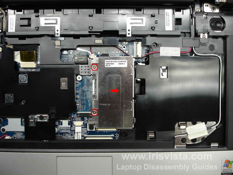
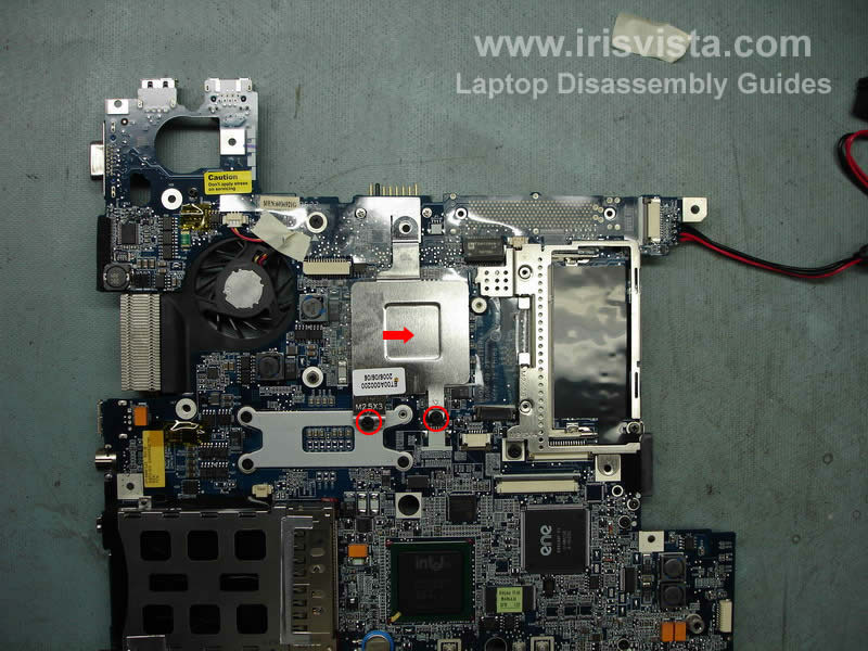
STEP 14
Remove two screws securing a metal plate over the memory module. Lift up and remove the plate.
|
| |
|
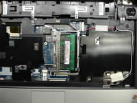 |
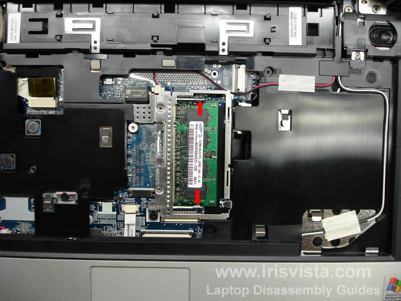
STEP 15
To remove the memory module, press the latches marked with red arrows. The memory module will pop up at 30 degrees angle. Grab the memory module and carefully pull it from the slot. |
| |
|
 |
STEP 16
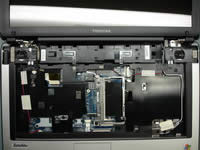
Now we are going to remove the notebook display assembly.
Remove the sticky tape securing the wireless card antenna cables and pull the cables through the opening in the laptop cover.
Unplug the video cable from the motherboard. When you unplug the cable, pull it by the edge, do not pull by the harness.
Remove two screws securing display hinges to the notebook base. |
| |
|
 |
STEP 17
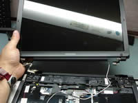
Carefully lift up the display assembly and put it aside. I'm not going to take it apart in this guide. |
| |
|
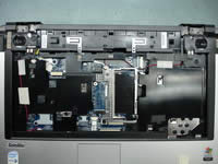 |
STEP 18
Now it's time to remove the top cover assembly.
Disconnect the speaker cables (red and black wires) from the motherboard.
Unlock touchpad cable connecotor and pull the cable.
Remove five screws marked with red circles. |
| |
|
 |
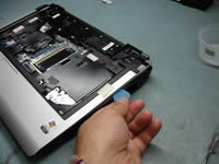
STEP 19
Start separating the top cover from the notebook base by disengaging the plastic latches in the battery bay. You can use a small flat-head screwdriver. |
| |
|
 |
STEP 20
To separate the top cover and the base I usually use a guitar pick. Insert the guitar pick between the top cover and the base and move it along the edge. |
| |
|
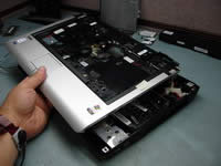 |
STEP 21
After all plastic latches are disengaged, you can lift up and remove the top cover assembly. |
| |
|
 |
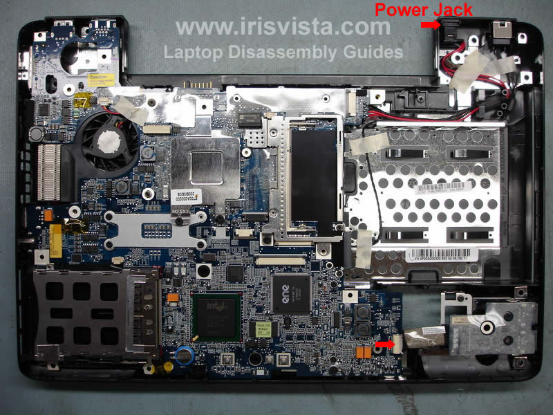
STEP 22
Remove the tape securing the power jack harness and lift up the power jack from the base (top arrow).
Unplug the USB board cable from the motherboard (bottom arrow). |
| |
|
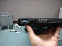 |
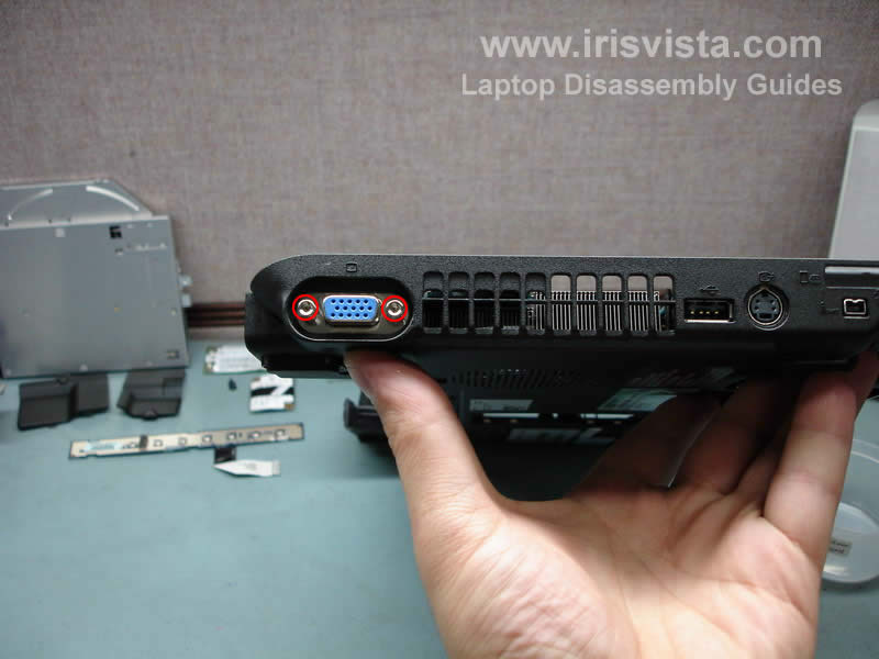
STEP 23
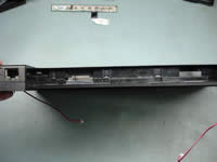
At this step remove two hex studs from the VGA connector on the side of the notebook. |
| |
|
 |
STEP 24
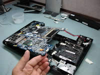
Now you can start removing the motherboard.
Start lifting it up on the right side. You'll have to flex the laptop base in order to release the volume wheel and the audio jacks.
After the volume wheel and the audio jacks are released, you can lift up the right side and remove the motherboard from the notebook base. |
| |
|
 |
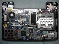
STEP 25
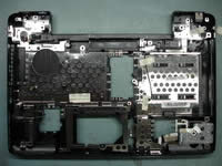
Here's a picture of the notebook base without the motherboard. |
| |
|
 |
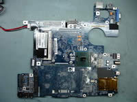
STEP 26
Remove two screws securing the cheap heatsink and lift it up. |
| |
|
 |
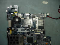
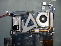
STEP 27
Remove the tape securing the cooling fan cables.
Unplug the fan cable from the motherboard.
Remove one screw securing the fan.
Turn the motherboard over. |
| |
|
 |
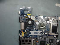
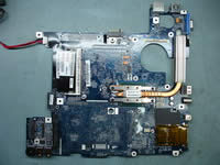
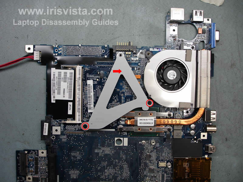
STEP 28
Remove two screws securing the triangle metal bracket.
Lift up and remove the bracket. |
| |
|
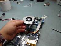 |
STEP 29
After the bracket is removed, you can remove the cooling fan. |
| |
|
 |
STEP 30
Remove four screws securing the CPU heatsink. All screws are numbered.
Start with screw 1 and finish with screw 4.
Lift up the heatsink and remove old thermal grease.
NOTE: you'll have to apply new layer of thermal grease before you assemble the laptop. Do not remove the heatsink if it's not necessary. |
| |
|
 |
STEP 31
Now, when the heatsink is removed you can access the notebook processor. To remove the processor, turn a lock (screw) on the side of the socket into "Open" position and carefully lift up the processor from the socket. |
| |
|
 |
STEP 32
Cool! All major components are removed and you can assemble it back. |
| |
|
|
|


