|
Toshiba Tecra A10, S10, Satellite S300 disassembly.
This guide has 3 pages:
PAGE 1: Removing keyboard and hard drive.
PAGE 2: Removing CD/DVD drive, memory modules, wireless card, motherboard.
PAGE 3: Removing video card, cooling fan assembly, processor, DC power jack. |
|
|
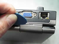 |
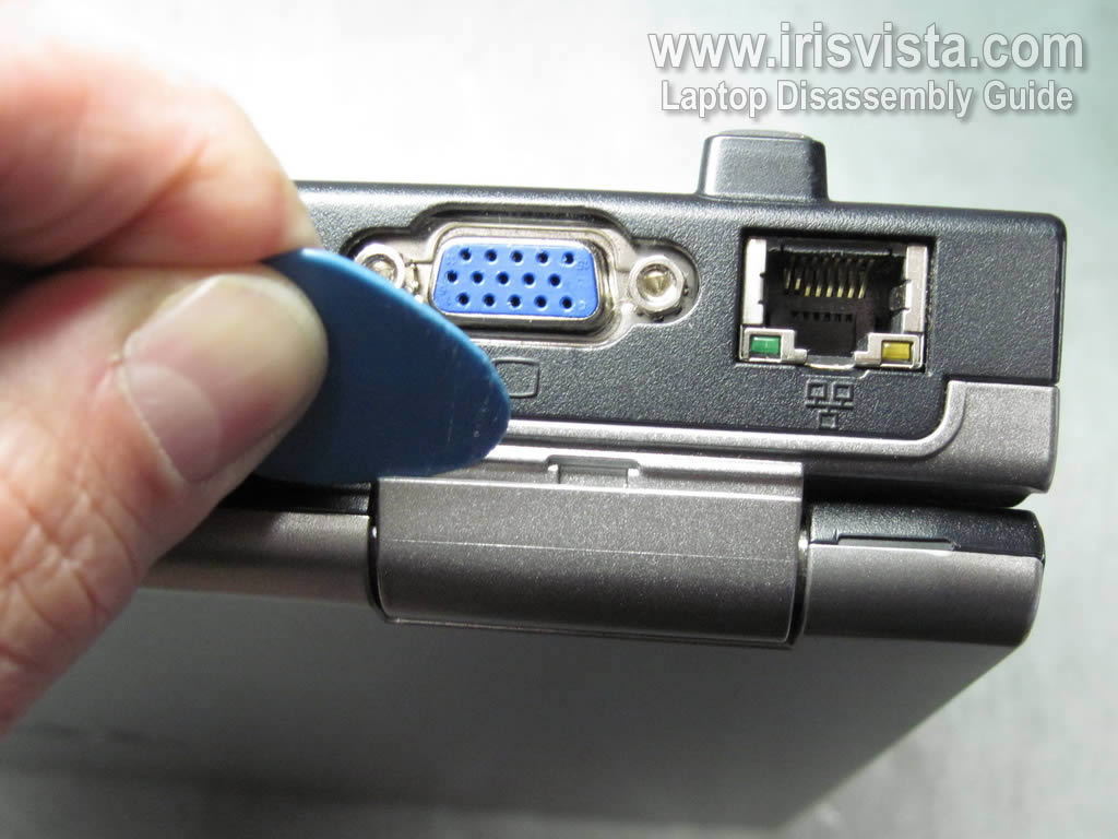
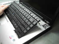
STEP 1
Turn off the laptop and remove the battery.
Using a guitar pick or another piece of soft plastic separate the hinge cover from the base.
This will make it easier to remove the keyboard bezel in the next step.
|
| |
|
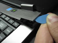 |
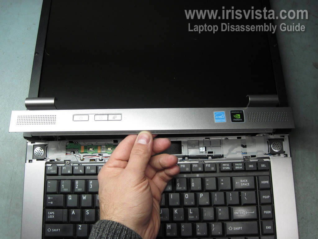
STEP 2
Lift up one side of the keyboard bezel and continue removing the bezel with your fingers.
|
| |
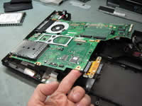
|
 |
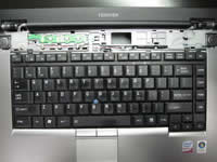
STEP 3
The keyboard bezel removed. |
| |
|
 |
STEP 4
Remove two screws securing the keyboard.
|
| |
|
 |
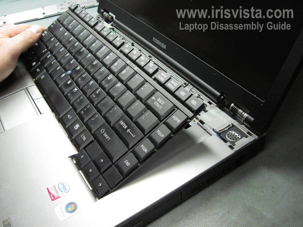
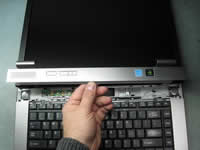
STEP 5
Carefully lift up the keyboard and place it upside down on the palm rest. |
| |
|
 |
STEP 6
Remove one screw securing the cable cover.
Slide the cover to the right and remove it from the laptop. |
| |
|
 |
STEP 7
Now you can access the keyboard cable connector.
Unlock the connector and pull the keyboard cable from the connector. |
| |
|
 |
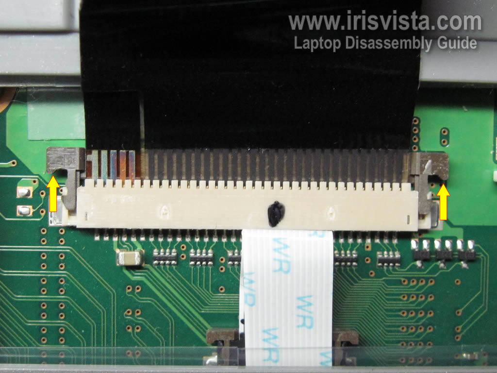
STEP 8
On this picture you can see the keyboard cable in the unlocked position.
In order to unlock the connector, move the brown clip about 2-3 millimeters towards the LCD screen.
The brown clip must stat attached to the white base.
After the connector is unlocked, you can release the cable and remove the keyboard. |
| |
|
 |
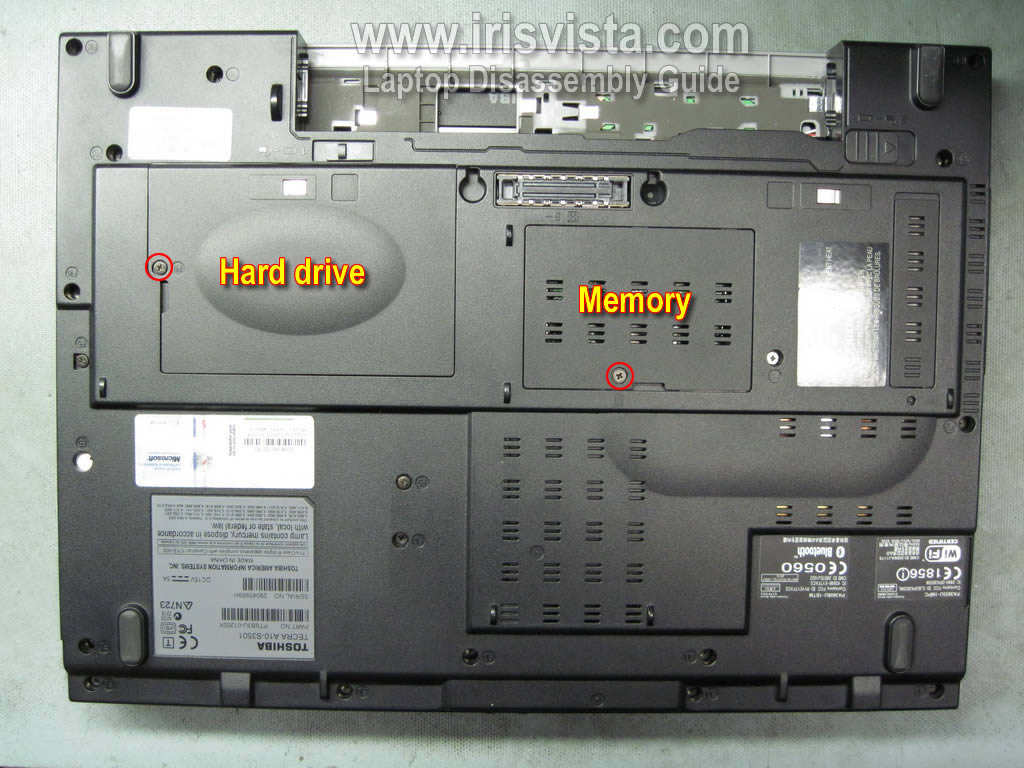
STEP 9
Turn the laptop upside down.
Remove the hard drive and memory covers. |
| |
|
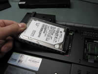 |
STEP 10
Lift up the left side of the hard drive assembly and disconnect cable on the right side.
Remove the hard drive assembly. |
| |
|
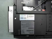 |
STEP 11
Remove two screws securing the CD/DVD drive.
Push the drive from the laptop with a screwdriver.
Remove the drive. |
| |
|
 |
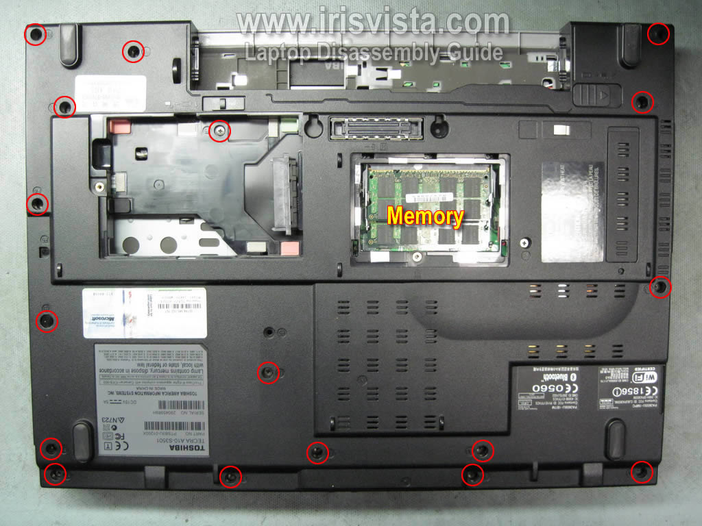
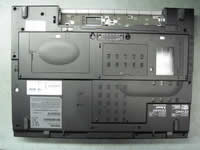
STEP 12
Remove all screws from the bottom of the laptop.
Remove both memory modules.
|
| |
|
 |
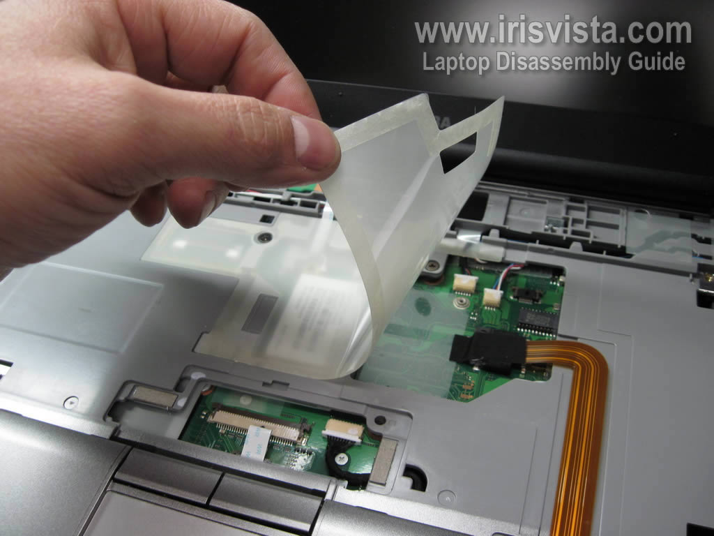
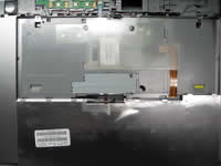
STEP 13
Remove clear protective film glued to the top cover.
|
| |
|
 |
STEP 14
Disconnect all cables from the motherboard. |
| |
|
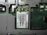 |
STEP 15
Disconnect two antenna cables from the wireless card.
Remove two screws securing the wireless card.
Remove the wireless card. |
| |
|
 |
STEP 16
Remove four screws securing the top cover assemble. |
| |
|
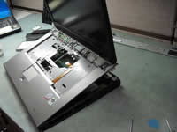 |
STEP 17
Start removing the top cover and display assembly from the laptop base. |
| |
|
 |
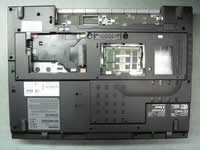
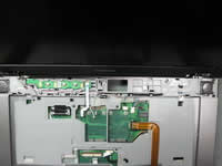
STEP 18
Top cover and display assembly removed. |
| |
|
 |
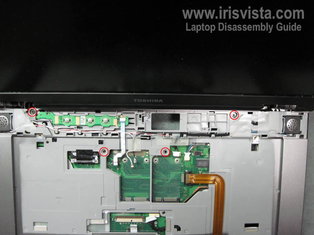
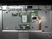
STEP 19
Remove four screws securing the motherboard.
Disconnect all cables pointed with yellow arrows.
By the way, you can access the CMOS battery without removing the motherboard. |
| |
|
 |
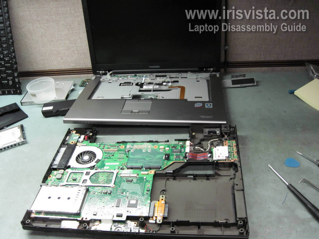
STEP 20
Lift up the right side of the motherboard. |
| |
|
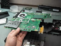 |
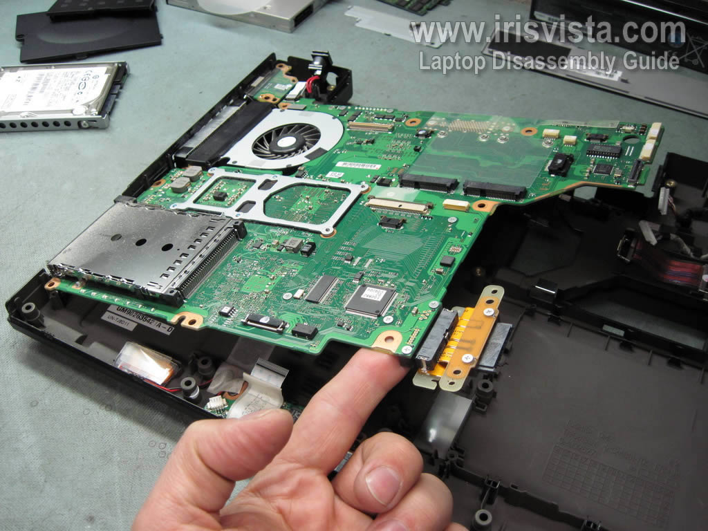
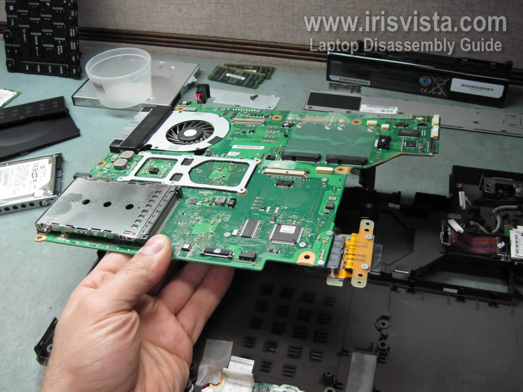
STEP 21
Remove motherboard from the laptop base. |
| |
|
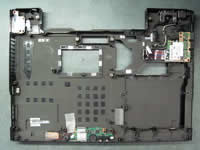 |
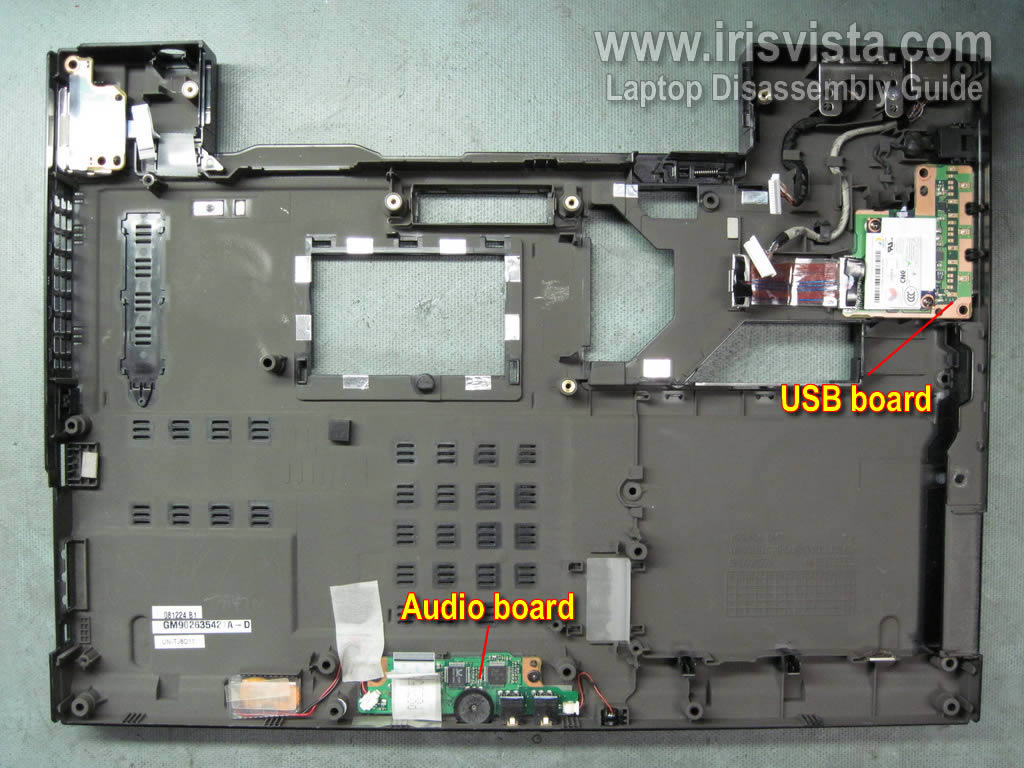
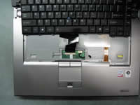
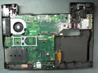
STEP 22
Here's the laptop base assembly without motherboard.
Now you can access and remove the audio board and USB board.
|
| |
|
 |
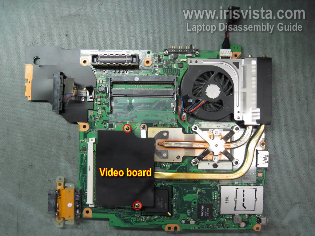
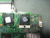
STEP 23
Remove two screws securing the video board assembly. |
| |
|
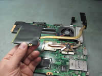 |
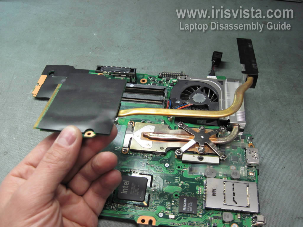
STEP 24
Remove video board assembly from the motherboard. |
| |
|
 |
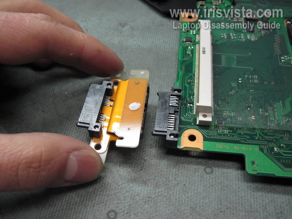
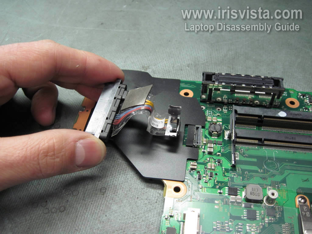
STEP 25
Remove the CD/DVD drive connector. |
| |
|
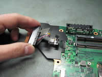 |
STEP 26
Disconnect and remove the hard drive cable.
|
| |
|
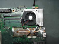 |
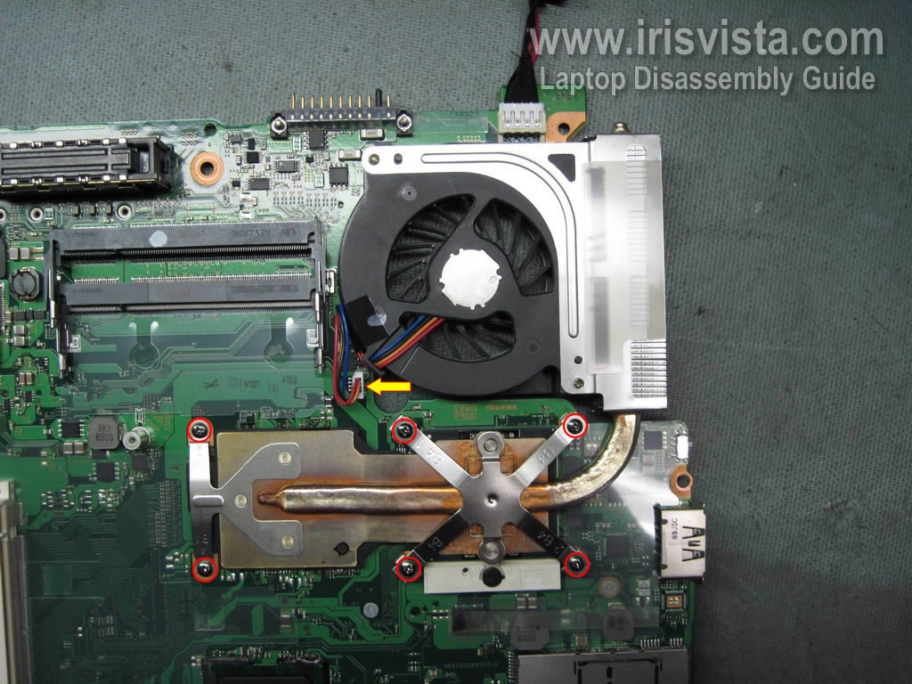
STEP 27
Remove six screws securing the cooling fan assembly.
Disconnect the cooling fan cable from the motherboard.
|
| |
|
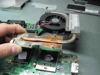 |
STEP 28
Remove the cooling fan assembly. |
| |
|
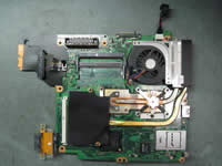
 |
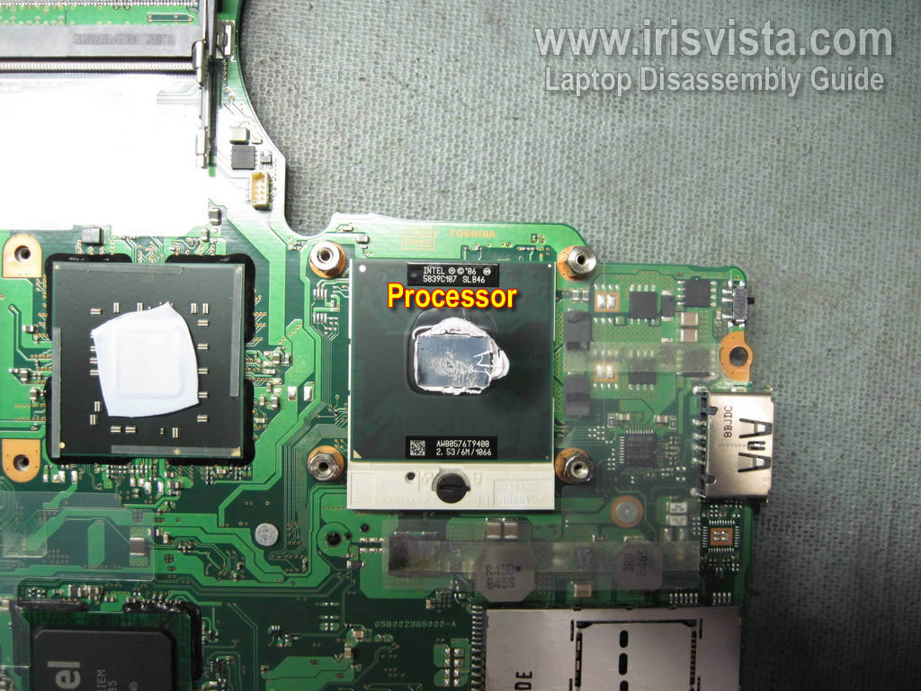
STEP 29
Now you can access and remove the processor. |
| |
|
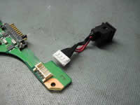 |
STEP 30
In this model the power jack harness can be unplugged from the motherboard without de-soldering. |
| |
|
|
|