|
Toshiba Tecra M1 disassembly.
This guide has three pages:
PAGE 1. Removing hard drive, DVD drive,modem, heat sink and keyboard bezel.
PAGE 2. Removing keyboard, memory modules and palm rest assembly (with touch pad).
PAGE 3. Removing wireless card, top cover assembly, motherboard and cooling fan. |
|
|
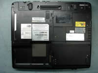 |
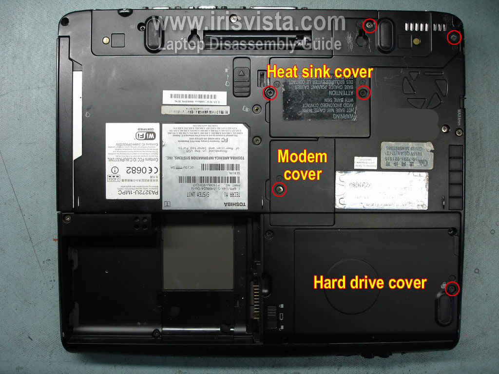
STEP 1
First of all, turn off the laptop and remove the battery.
Remove four screw securing the heat sink cover. Remove the cover.
Remove one screw securing the modem cover. Remove the cover.
Remove one screw securing the hard drive cover. Remove the cover.
|
| |
|
 |
STEP 2
Move the DVD lock into the open position (green arrow) and pull the DVD drive from the laptop.
The DVD drive might be secured by one screw under the lock. Remove the screw if needed.
Remove two screw securing the modem card. Lift up the modem card and disconnect the cable.
Slide the hard drive assembly to the right and disconnect it from the motherboard. Remove the hard drive assembly.
|
| |
|
 |
STEP 3
Remove four screws securing the heat sink bracket. Remove the bracket.
Lift up and remove the heat sink.
Now you can get access to the CPU. |
| |
|
 |
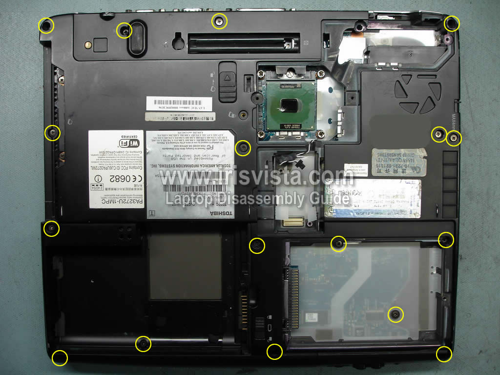
STEP 4
Remove all screws from the bottom of the notebook. |
| |
|
 |
STEP 5
In the following 5 steps I'll be removing the keyboard.
Lift up the switch button cover. Continue removing the cover with your fingers. |
| |
|
 |
STEP 6
Remove the switch button cover from the laptop.
|
| |
|
 |
STEP 7
Remove three screws securing the keyboard.
Remove the metal plate located above the F8 key.
Remove the keyboard and place it upside down on the palm rest. |
| |
|
 |
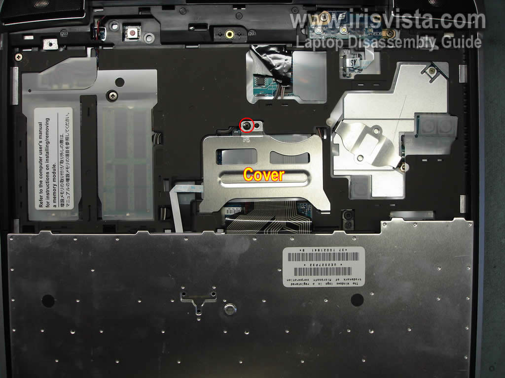
STEP 8
Remove one screw securing the keyboard cable connector.
Remove the cover. |
| |
|
 |
STEP 9
In order to unlock the keyboard connector, move the brown clip about 2 millimeters towards the LCD screen.
The brown clip must stat attached to the connector base.
Now you can pull the cable and remove the keyboard.
|
| |
|
 |
STEP 10
Remove two screws securing the power button board.
Disconnect the power button cable from the motherboard.
Remove the power button board. |
| |
|
 |
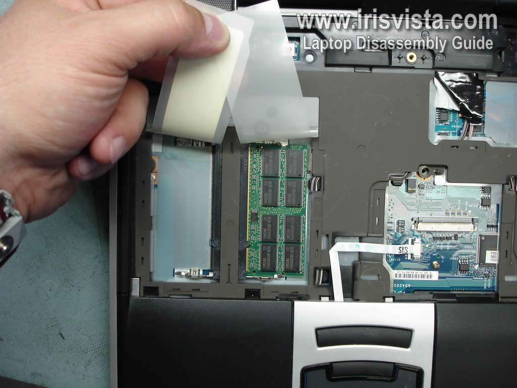
STEP 11
Both memory slots could be access under the keyboard.
In my case there is only one memory module installed.
Remove the memory module. |
| |
|
 |
STEP 12
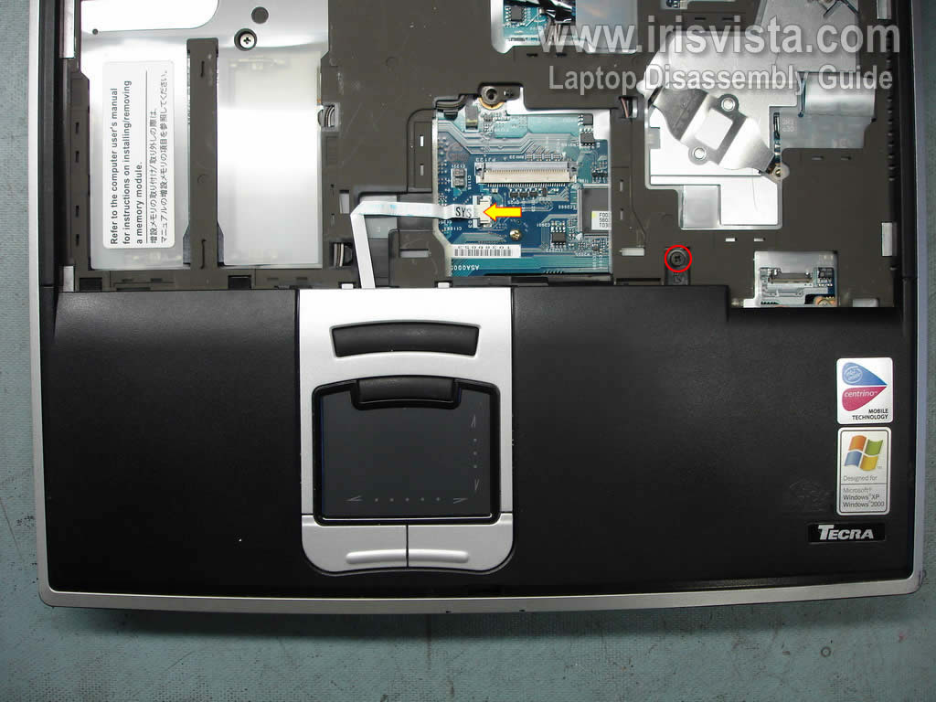
Remove one screw securing the palm rest assembly.
Disconnect the touch pad cable from the motherboard. |
| |
|
 |
STEP 13
Remove the touch pad assembly. |
| |
|
 |
STEP 14
Disconnect two antenna cables from the wireless card (green arrows). Remove the wireless card.
Disconnect one cable from the motherboard.
|
| |
|
 |
STEP 15
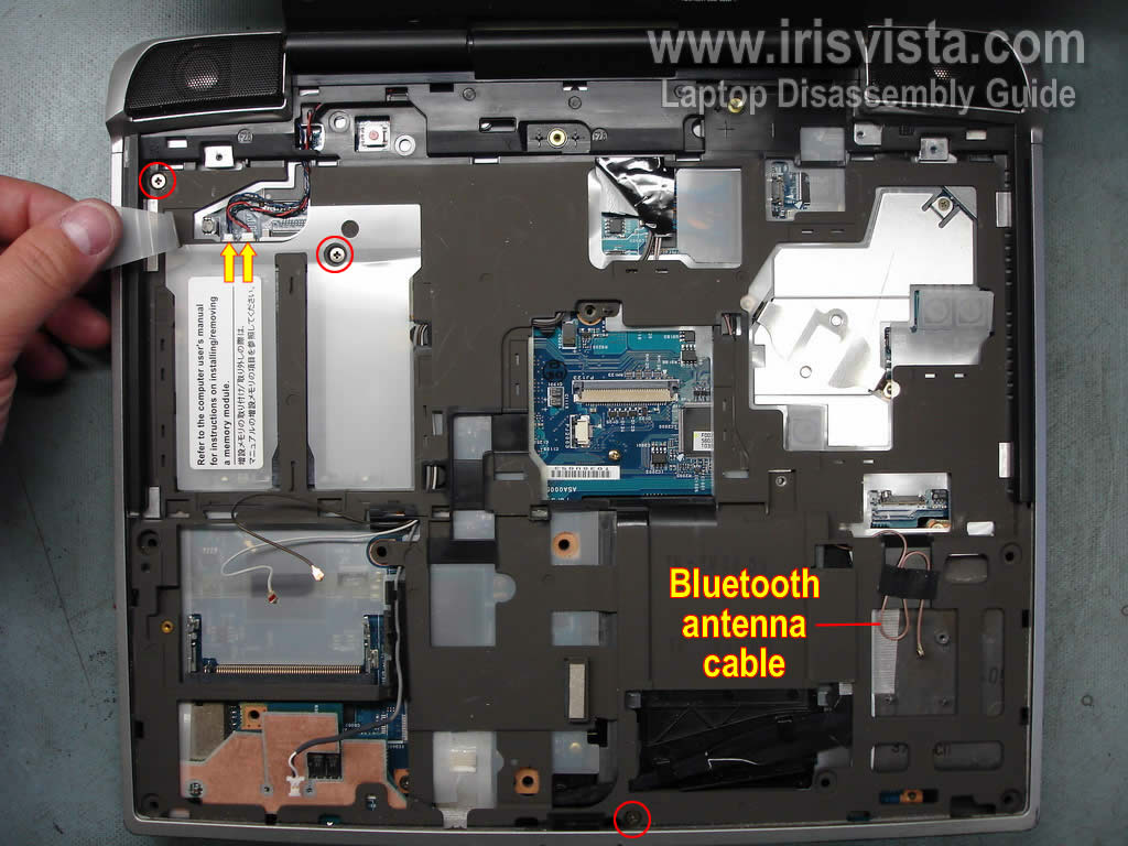
Remove three screws securing the top cover assembly.
Disconnect both speaker cables from the motherboard.
In my laptop I don't have the Bluetooth module installed. That's why the brown antenna cable is taped to the top cover. |
| |
|
 |
STEP 16
Carefully lift up and remove the top cover and LCD assembly. |
| |
|
 |
STEP 17
Remove one screw securing the audio board. Lift up and remove the audio board.
Remove one screw securing the LED board. Disconnect the LED board cable from the motherboard.
Remove the LED board.
|
| |
|
 |
STEP 18
Remove three screws securing the motherboard.
Disconnect three cables.
|
| |
|
 |
STEP 19
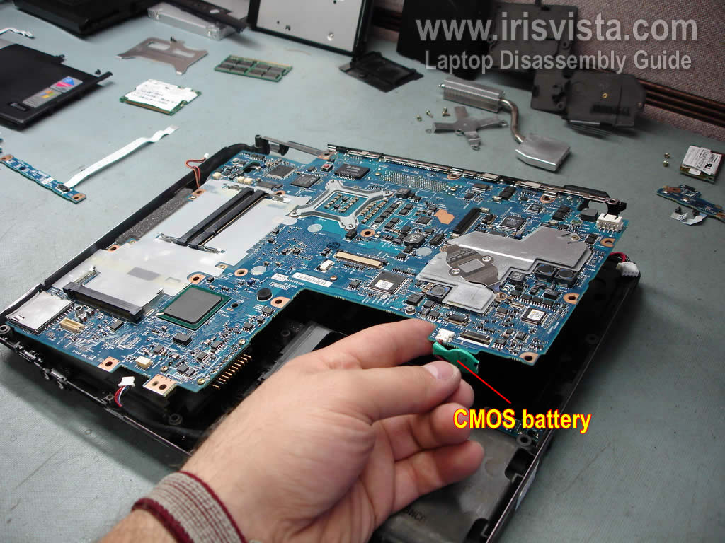
Remove the motherboard from the notebook base.
The CMOS battery is still attached to the motherboard. |
| |
|
 |
STEP 20
Finally, you can access and remove the cooling fan.
Remove two screws securing the fan. Remove and replace the fan if needed. |
| |
|
|
|