|
Toshiba Tecra M7, Satellite R20 disassembly.
The keyboard removal and replacement procedure explained in steps 5-9.
The CD/DVD drive removal procedure explained in steps 10-12.
Both emory modules are accessed in step 9.
The cooling fan is removed in the step 19.
|
|
|
 |
STEP 1
Turn off the laptop, unplug the power adapter and remove the battery.
Remove one screw securing the mode cover. Remove the cover.
Remove two screws securing the hard drive cover. Remove the cover.
|
| |
|
 |
STEP 2
Lift up the hard drive and slide it to the left to disconnect from the connector.
Remove the hard drive.
Remove two screws securing the dial-up modem card.
|
| |
|
 |
STEP 3
Lift up modem card to disconnect it from the motherboard.
Disconnect the modem cable. |
| |
|
 |
STEP 4
Remove all screws from the bottom of the laptop.
|
| |
|
 |
STEP 5
Insert a small flat head screwdriver between the bezel and keyboard.
Carefully lift up one side of the bezel.
Continue removing bezel with your fingers.
|
| |
|
 |
STEP 6
The keyboard bezel has been removed.
|
| |
|
 |
STEP 7
Now you can access two screws securing the keyboard.
Remove both screws, press on the lock above the F8 key and release the keyboard.
Remove keyboard from the laptop and place it upside down on the palm rest.
|
| |
|
 |
STEP 8
Remove two screws securing the memory cover.
Remove one screw securing the keyboard connector cover.
Remove both covers. |
| |
|
 |
STEP 9
As you see on this picture, both memory slots were hidden under the keyboard.
Remove both memory modules.
Unlock the keyboard connector by moving the brown locking clip to the direction shown by two arrows. Move the clip about 1-2 millimeters, not more. It must say attached to the connector base.
Release the keyboard cable and remove the keyboard. |
| |
|
 |
STEP 10
Remove one screw securing the DVD drive (green).
Remove one screw securing the top cover assembly (red).
Disconnect the blue cable from the motherboard. |
| |
|
 |
STEP 11
Remove the display hinge cover.
Remove two screws securing the hinge.
|
| |
|
 |
STEP 12
Push the CD/DVD drive from the laptop. Remove the drive.
If you are only replacing the CD/DVD drive, you have to go through:
STEPS 5-9 to remove the keyboard.
STEP 10 to remove the screw securing the CD/DVD drive.
STEP 12 to remove the drive. |
| |
|
 |
STEP 13
Turn the laptop upside down and start removing the base cover. |
| |
|
 |
STEP 14
The base cover has been removed. |
| |
|
 |
STEP 15
Remove the audio jack cover.
Disconnect the microphone cable from the motherboard.
Remove the cover. |
| |
|
 |
STEP 16
Remove one screws securing the metal plate above the wireless card.
Most likely you have a security torx screw installed. You can remove this screw with a small flat head screwdriver. |
| |
|
 |
STEP 17
Disconnect both antenna cables from the wireless card.
Remove one screw securing the wireless card to the motherboard.
Remove the card. |
| |
|
 |
STEP 18
Disconnect one cable from the motherboard.
|
| |
|
 |
STEP 19
Remove three screws securing the cooling assembly (fan and heat sink).
Disconnect the cooling fan cable from the motherboard.
Lift up and remove the cooling assembly. |
| |
|
 |
STEP 20
Disconnect four connectors. The green arrow points to the DC-IN jack harness.
In this model the DC jack is plugged into the motherboard. If the jack is broken, you simply unplug the bad one from the motherboard and replace it with a new one. No soldering job needed.
Remove one screw securing the plastic tray. |
| |
|
 |
STEP 21
Move all unplugged cables aside as it shown on this picture. |
| |
|
 |
STEP 22
Remove one screw securing the motherboard.
|
| |
|
 |
STEP 23
Lift up the motherboard and remove it from the cover. |
| |
|
 |
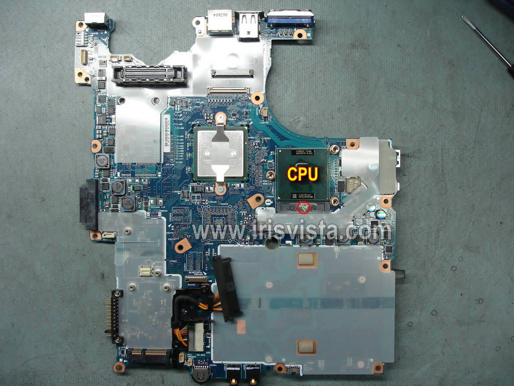
STEP 24
The motherboard has been remove and ready to be replaced with a new one if needed.
In order to remove the processor (CPU) unlock the socket and lift up the processor. |
| |
|
|
|