|
How to take apart Toshiba Satellite M70.
Thank you Bill (fog.locker_at_shaw.ca) for submitting this disassembly guide. |
|
|
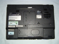 |
STEP 1
- Turn the laptop upside down.
- Unlock the battery (if locked) and remove it.
|
| |
|
 |
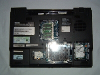
STEP 2
- Remove one screw from the memory module cover.
- Remove three screws from the modem/hard drive bay cover.
- Remove one Torx T-9 screw from the wireless card cover.
|
| |
|
 |
STEP 3
- Release the memory module(s) locking tabs and remove memory module(s).
- Remove two screws from hard drive, pull it to the right using fitted black vinyl pull tab, then lift it out.
- Remove one screw securing the modem.
- Lift the modem up and to the right to disconnect it from the system board.
- Unplug the cable on the modem card (inset). Note the orientation of connector.
|
| |
|
 |
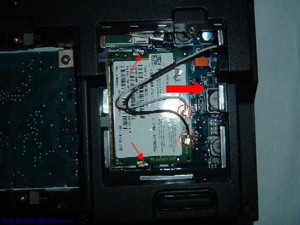
STEP 4
- Carefully disconnect the wireless card antenna cables. Note that the white cable goes to MAIN and black cable goes to AUX.
- Release the card locking tabs.
- Remove the wireless card from the laptop. |
| |
|
 |
STEP 5
- Remove one screw securing the DVD drive.
- Push on the grey metal tab to release the drive, and slide it out.
|
| |
|
 |
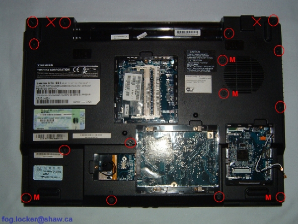
STEP 6
- Remove the 15 circled screws on the bottom of the case. The screws marked with an "M" are shorter than the others.
- Do NOT remove the two crossed-out screws; they secure the hinges and will be removed in a later stage.
|
| |
|
|
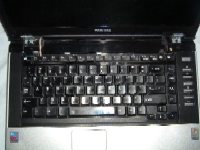
STEP 7
- Lift the keyboard securing strip with a sharp object and continue removing with your fingers. The strip should rotate from the back toward the front. NOTE: It is eaiser to remove the strip if one starts at each side and works toward the middle.
|
| |
|
 |
STEP 8
- Remove the keyboard securing strip.
|
| |
|
 |
STEP 9
- Remove the two screws securing the keyboard.
|
| |
|
 |
STEP 10
- Lift up the keyboard.
- Slide the keyboard connector's white release tabs forward, then disconnect the flat keyboard cable from the system board. |
| |
|
 |
STEP 11
- Carefully lift and remove the keyboard left trim piece. |
| |
|
 |
STEP 12
- Remove two screws securing the display on the bottom of the laptop.
|
| |
|
 |
STEP 13
- Carefully pull the wireless antenna cables through the opening and out of the channel.
- Unplug the video cable.
- Remove the two screws securing the LCD panel assembly.
|
| |
|
|
STEP 14
- Lift up the LCD panel assembly and remove it from the laptop.
|
| |
|
 |
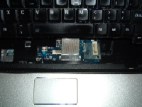
STEP 15
- Slide the media panel connector's grey release tabs to the right, and disconnect the media panel ribbon cable.
- Slide the touchpad connector's grey release tabs toward you, and using the blue pull tab, disconnect the touchpad ribbon cable.
- Remove four screws on the front and one silver screw in the hard drive bay on the back (see inset) securing the system board.
|
| |
|
 |
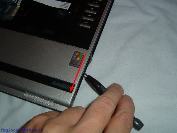
STEP 16
- Carefully work a thin, flat object such as a small flat-blade screwdriver, around the edge between the top cover and the laptop base. Guitar picks are reportedly very good for this purpose.
|
| |
|
 |
STEP 17
- Lift up and remove the top cover assembly. |
| |
|
 |
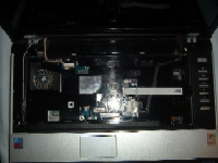
STEP 18
- Disconnect the speaker cable on the system board. |
| |
|
 |
STEP 19
- Remove four small screws securing the bracket over the ExpressCard slot, and lift off the bracket.
|
| |
|
|
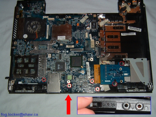
STEP 20
- Remove six screws securing system board and ExpressCard module to laptop base.
- Remove wireless ON/OFF switch faceplate (edge view, inset).
|
| |
|
 |
STEP 21
- Remove two hex studs.
|
| |
|
 |
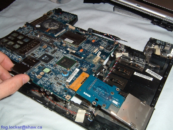
STEP 22
- Carefully lift up the system board and remove it from the laptop base.
|
| |
|
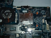 |
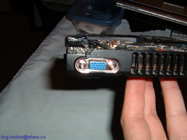
STEP 23
- The video chip is under the heatsink on the top of the system board.
- Remove one screw to access the video chip. |
| |
|
 |
STEP 24
- The CPU is located under the X-shaped heatsink on the underside of the system board.
- CPU fan and CPU removal is not discussed in this disassembly guide.
|
| |
|
|
|