|
Toshiba Satellite U505, U505D, U500, U500D disassembly. |
|
|
 |
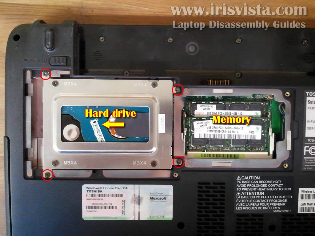
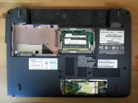
STEP 1
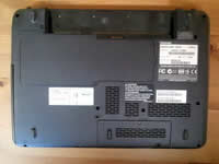
Start laptop disassembly with removing the battery.
On the bottom you'll find two cover. One for the hard drive and memory and another one for the wireless card.
Remove screws securing both covers. Lift up and remove both covers.
|
| |
|
 |
STEP 2
There are four screws securing the hard drive mounting bracket to the laptop base.
Remove four screws and slide the hard drive to the left. This will disconnect the hard drive from the motherboard.
|
| |
|
 |
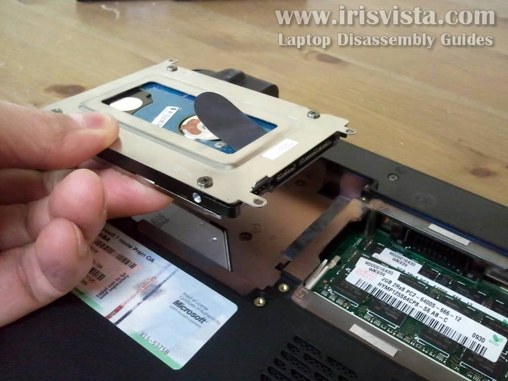
STEP 3
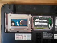
Lift up and remove the hard drive assembly. It's not necessary to remove memory modules for the purpose of my guide, so I'll leave them installed.
My Toshiba Satellite U505 laptop had a regular 2.5" SATA hard drive installed. You can replace it with any other large size 2.5" SATA hard drive or 2.5" SSD.
Toshiba Satellite U505 laptop can handle up to 8GB RAM. You can install up to 4GB RAM module into each slot.
Memory type: DDR2 PC2-6400. |
| |
|
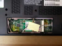 |
STEP 4
The wireless card secured under the small cover. It's not necessary to remove the wireless card for the purpose of my guide.
If you would like to remove the card you'll have to disconnect two antenna cables, remove two screws securing the card and pull the card from the slot the same way you pull memory modules. |
| |
|
 |
STEP 5
Remove one screw securing the optical DVD drive.
Slide DVD drive to the left to disconnect it from the motherboard. Pull and remove the drive. |
| |
|
 |
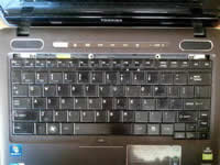
STEP 6
Remove two screws located in the battery compartment.
These screws securing the keyboard bezel. |
| |
|
 |
STEP 7
Follow steps 7-14 from removing and replacing the keyboard.
Lift up one side the keyboard bezel with a small screwdriver. Continue removing the bezel with your fingers.
There are a few plastic latches securing the bezel so you'll have to wiggle it a little bit to disengage latches. |
| |
|
 |
STEP 8
Remove two screws securing the keyboard to the laptop base. |
| |
|
 |
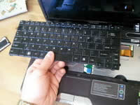
STEP 9
Carefully lift up the upper side of the keyboard and turn it over.
Place the keyboard upside down on the palmrest. |
| |
|
 |
STEP 10
The keyboard connected to the motherboard via two cables.
The wide cable transfers signal from keystrokes to the motherboard.
The narrow cable I believe is for the backlight.
Before you remove both cables you'll have to unlock connectors. I'll show how to do it in the following three steps. |
| |
|
 |
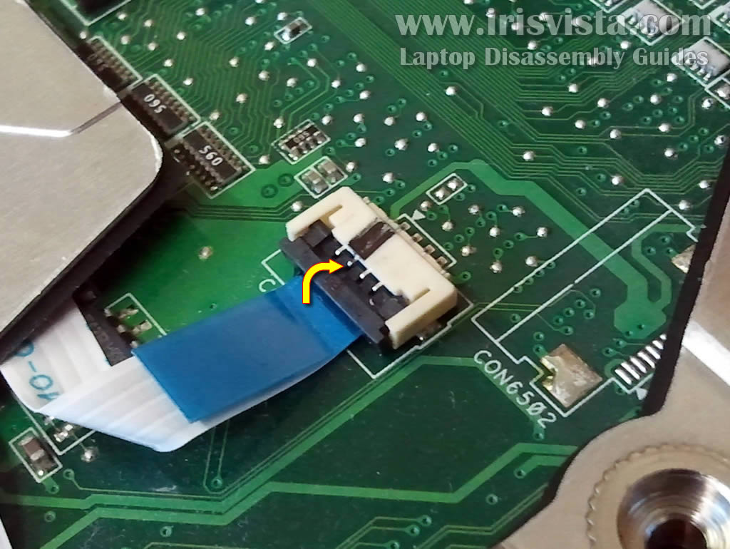
STEP 11
Here's how you unlock the wide cable connector.
Move the brown locking tab about 1-2 millimeters to the shown direction. The locking tab must stay attached to the connector base.
After the connector is unlocked, pull the keyboard cable. |
| |
|
 |
STEP 12
Here's how to unlock the small connector.
Lift up the left side of the locking tab with your fingernail. The tap will open up at a 90 degree angle and release the cable. |
| |
|
 |
STEP 13
After the connector is unlocked, pull the cable.
|
| |
|
 |
STEP 14
Now you can remove the keyboard. |
| |
|
 |
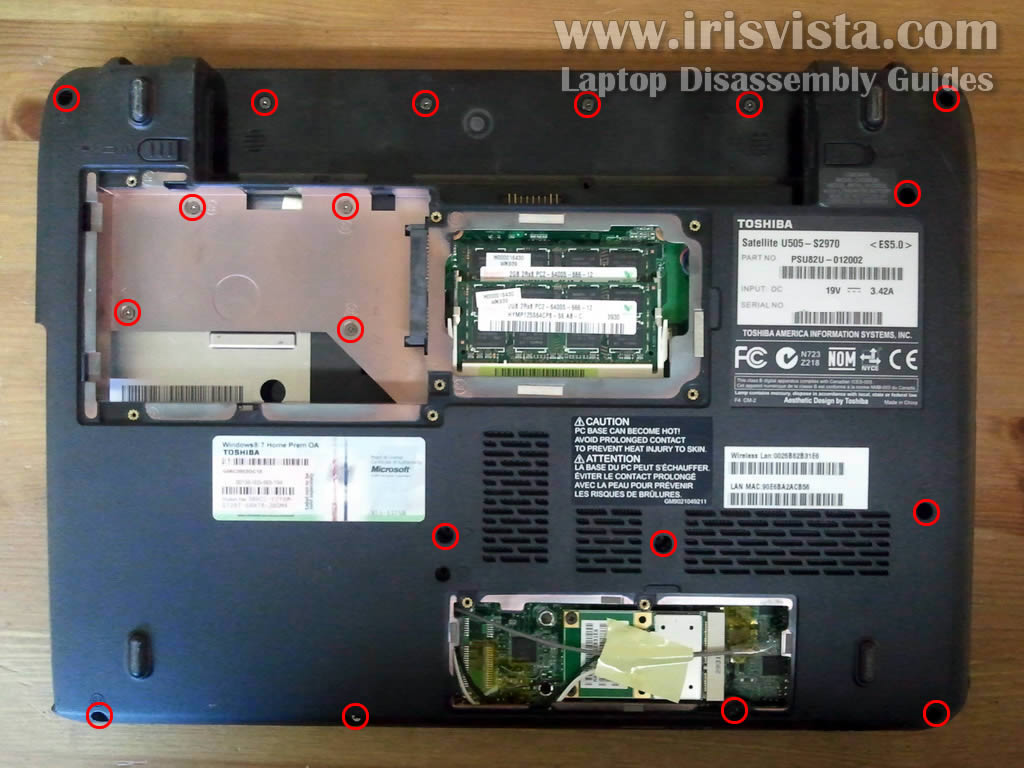
STEP 15
In the following six steps I explain how to remove the top cover assembly.
Remove all screws from the bottom of the laptop. These screws securing the top cover. |
| |
|
 |
STEP 16
Now remove four more screws on the other side.
Disconnect four cables. |
| |
|
 |
STEP 17
You disconnect top cover cables the same way you disconnected the small keyboard cable.
Unlock the connector by lifting up the locking tab. |
| |
|
 |
STEP 18
Pull the cable from the connector. |
| |
|
 |
STEP 19
Now you can start removing the top cover assembly.
Lift up one side of the cover with your fingers. |
| |
|
 |
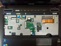
STEP 20
The top cover assembly removed. |
| |
|
 |
STEP 21
Under the top cover assembly can access the following internal laptop components:
- motherboard
- cooling fan
- CMOS battery (soldered to the motherboard)
- laptop speakers
- LAN board
- DC jack harness
In order to remove the cooling fan it will be necessary to disconnect and remove the motherboard. |
| |
|
|
|