|
Toshiba Tecra A9, S5, P5, Satellite Pro S200 disassembly.
|
|
|
 |
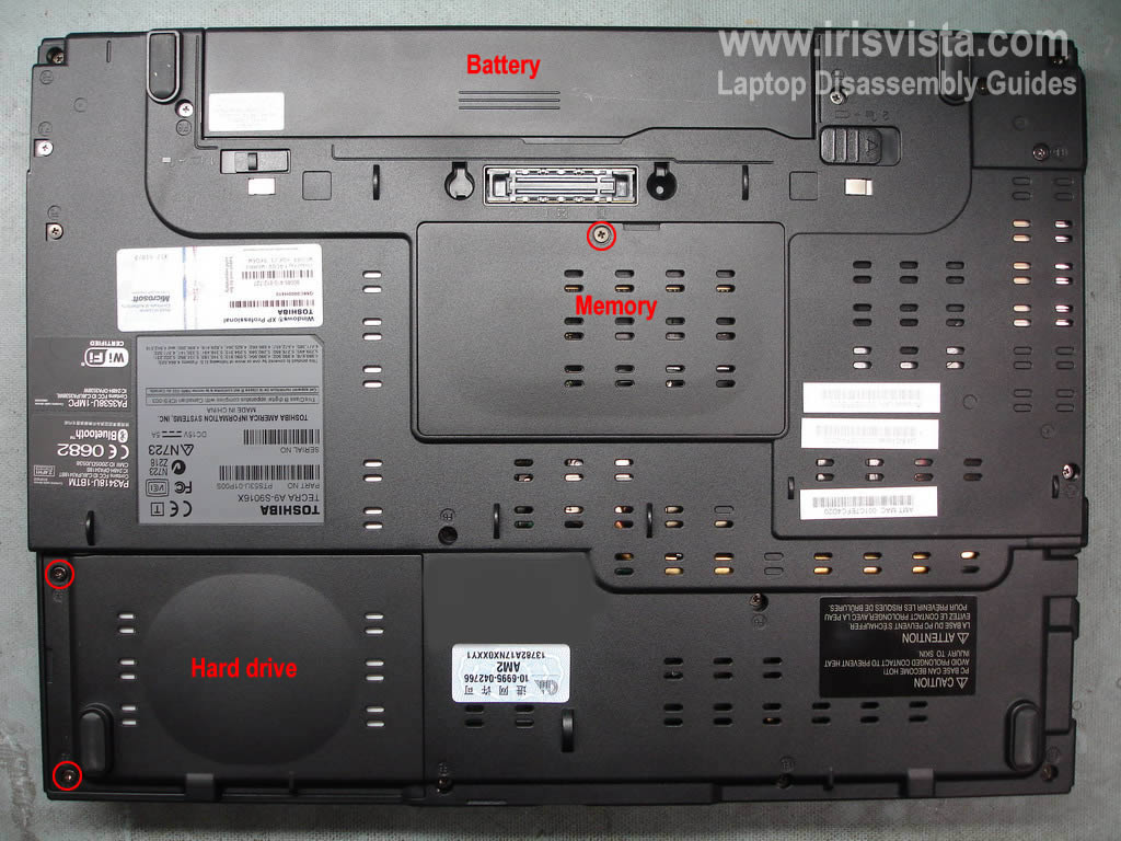
STEP 1
Remove laptop battery.
Remove hard drive cover.
Remove memory and modem cover.
|
| |
|
 |
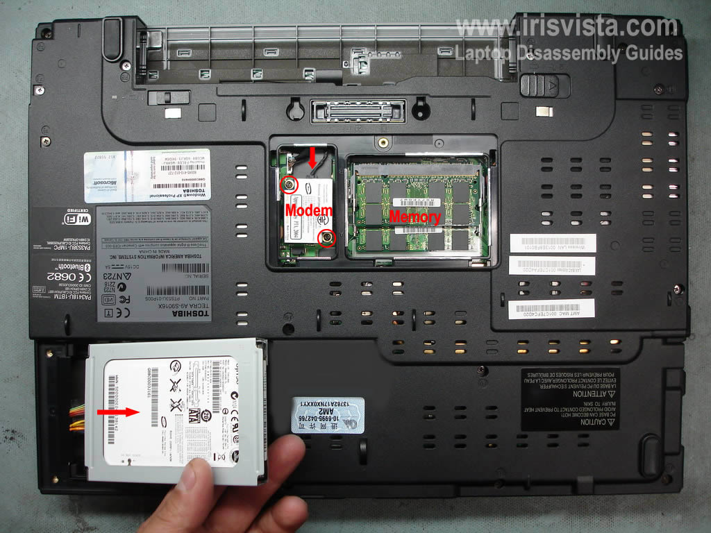
STEP 2
Lift up the hard drive and carefully disconnect the cable on the left side.
Remove the hard drive.
Remove two screws securing the modem card. Lift up the modem and disconnect the cable.
Remove both memory modules.
|
| |
|
 |
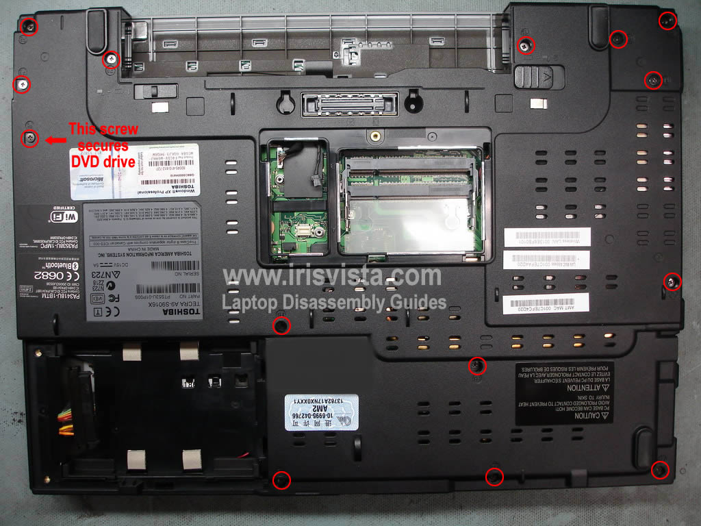
STEP 3
Remove all screws from the bottom of the laptop. |
| |
|
 |
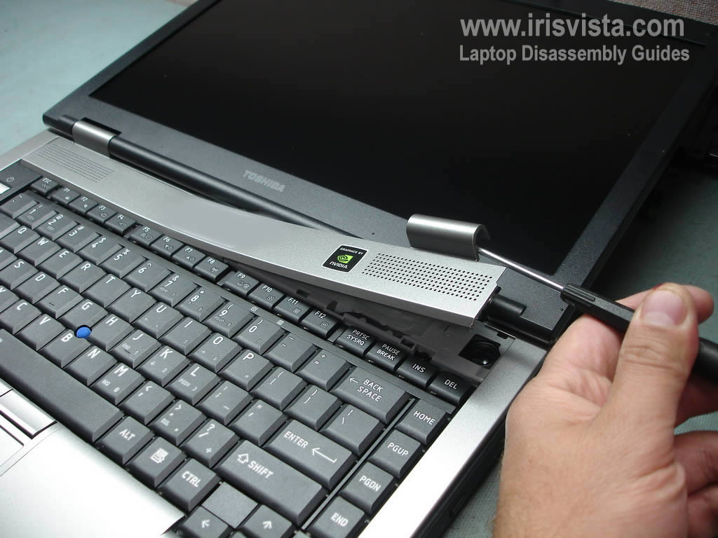
STEP 4
Turn the laptop over.
Using a small flathead screwdriver remove the keyboard bezel. |
| |
|
 |
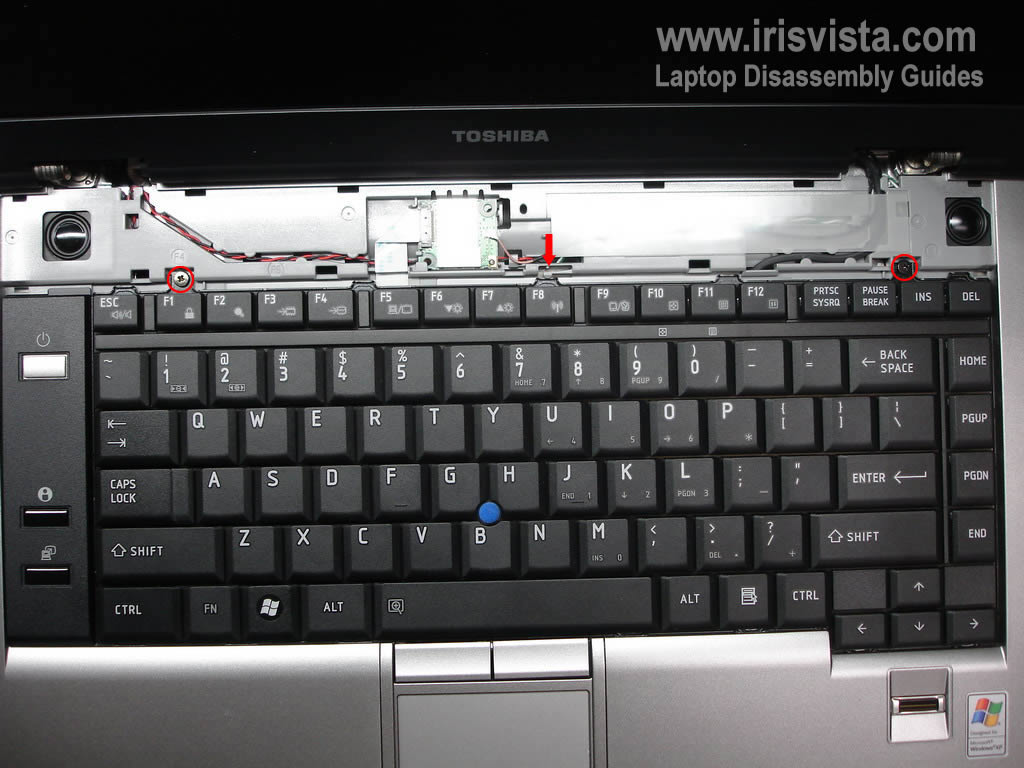
STEP 5
Remove two screws securing the keyboard.
Unlock the latch.
Lift up the keyboard and turn it over.
|
| |
|
 |
STEP 6
Remove one screw securing the keyboard connector cover.
Remove the cover.
|
| |
|
 |
STEP 7
Open up the keyboard connector on the motherboard.
Be careful, if you break the connector you'll have to replace the motherboard.
Pull the keyboard cable and remove the keyboard.
Remove protective film.
If you replacing the keyboard, simply follow steps 4-7. You don't have to remove screws from the bottom of the laptop. |
| |
|
|
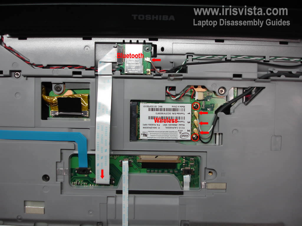
STEP 8
Disconnect the Bluetooth card cable from the motherboard and unplug the brown antenna cable from the card.
Release the Bluethooth card and remove it.
Unplug three antenna cables from the wireless card.
Remove two screws securign the wireless card and remove the card. |
| |
|
 |
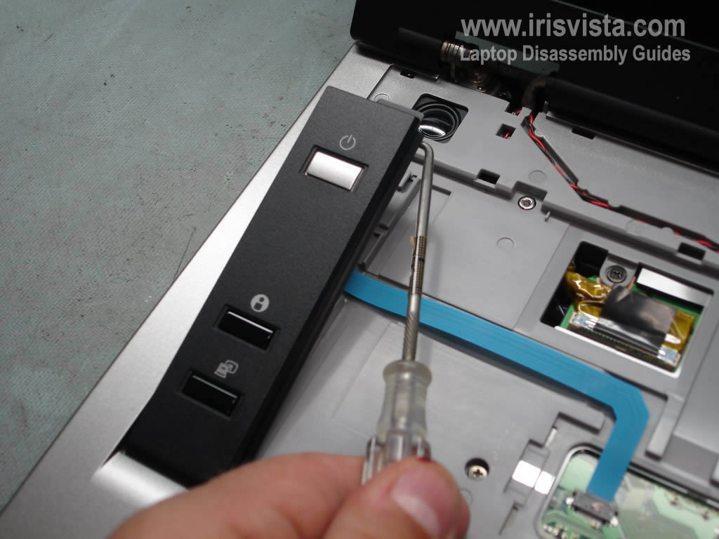
STEP 9
Remove the power button board cover.
|
| |
|
 |
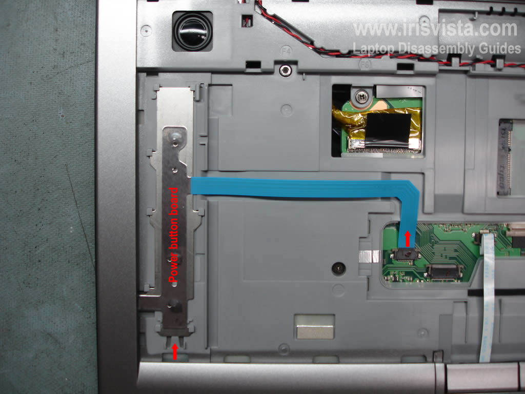
STEP 10
Unplug the power button board cable from the motherboard.
Press on the lock and slide the power button board down.
Remove the board. |
| |
|
 |
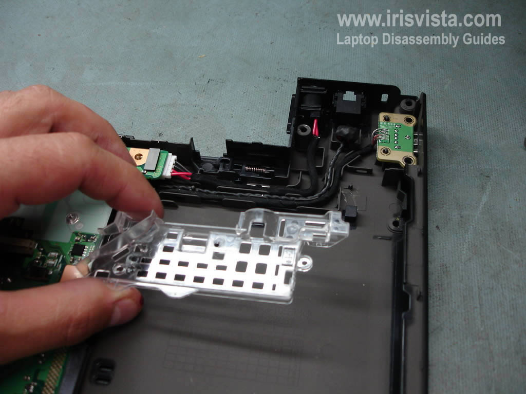
STEP 11
Carefully remove the touch pad cover. |
| |
|
 |
STEP 12
Remove one screw securing the touch pad assembly.
Disconnet the touch pad cable from the motherboard.
Remove touch pad assembly. |
| |
|
 |
STEP 13
Disconnect video cable from the motherboard.
Disconnect speaker cable from the motherboard.
Remove three screws securing the top cover assembly. |
| |
|
 |
STEP 14
Push the DVD from the laptop with a screwdriver. Remove DVD drvie.
The DVD drive is secured by two screws.
One screw is located on the bottom of the laptop and shown in the step 3.
The second screw is located under the keyboard and shown in the stwp 13.
|
| |
|
 |
STEP 15
Start removing the top cover assembly with the display.
The display is still attached to the top cover. |
| |
|
|
STEP 16
Remove the top cover assembly. |
| |
|
 |
STEP 17
The top cover has been removed. |
| |
|
 |
STEP 18
Remove the cable cover. |
| |
|
 |
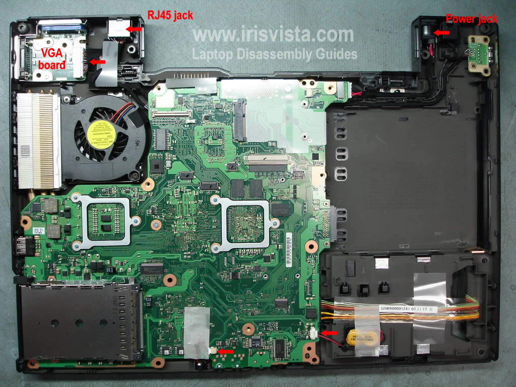
STEP 19
Unplug cable from the VGA board.
Lift up and release the RJ45 jack.
Lift up and release the power jack.
Disconnect the CRT battery from the motherboard.
Disconnect the microphone cable. |
| |
|
 |
STEP 20
Carefully lift up and remove the motherboard. |
| |
|
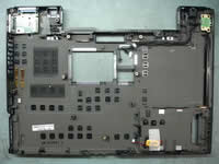 |
STEP 21
The base assembly without motherboard. |
| |
|
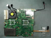 |
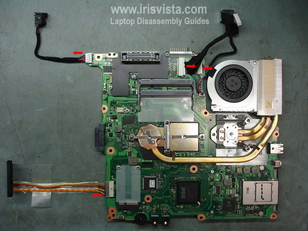
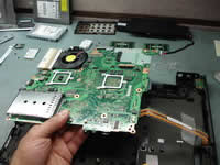
STEP 22
The motherboard has been removed.
Turn it over.
|
| |
|
 |
STEP 23
Disconnect the power jack cable.
Disconnect the hard drive cable.
Disconnect the VGA board cable.
Disconnect the RJ45 cable.
|
| |
|
|
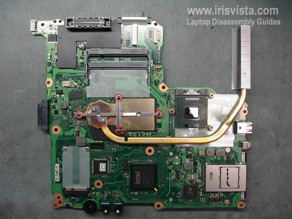
STEP 24
Remove three screws securing the CPU heatsink>
Disconnect the cooling fan from the motherboard. |
| |
|
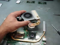 |
STEP 25
Lift up and remove the cooling fan with the heatsink. |
| |
|
 |
STEP 26
Remove four screw securing the VGA chip heatsink. |
| |
|
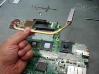 |
STEP 27
Lift up and remove the heatsink. |
| |
|
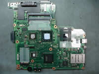 |
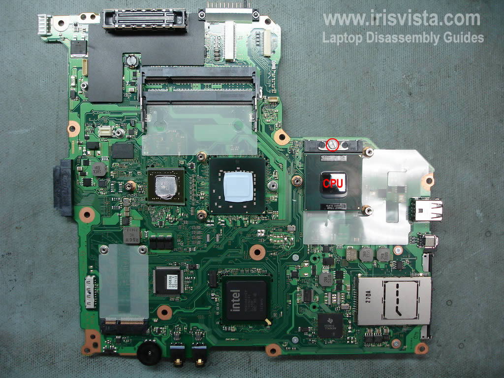
STEP 28
Unlock the CPU socket.
Lift up and remove the CPU. |
| |
|
|
|