|
Toshiba Satellite L675D, L675, L670D, L670 disassembly. |
|
|
 |
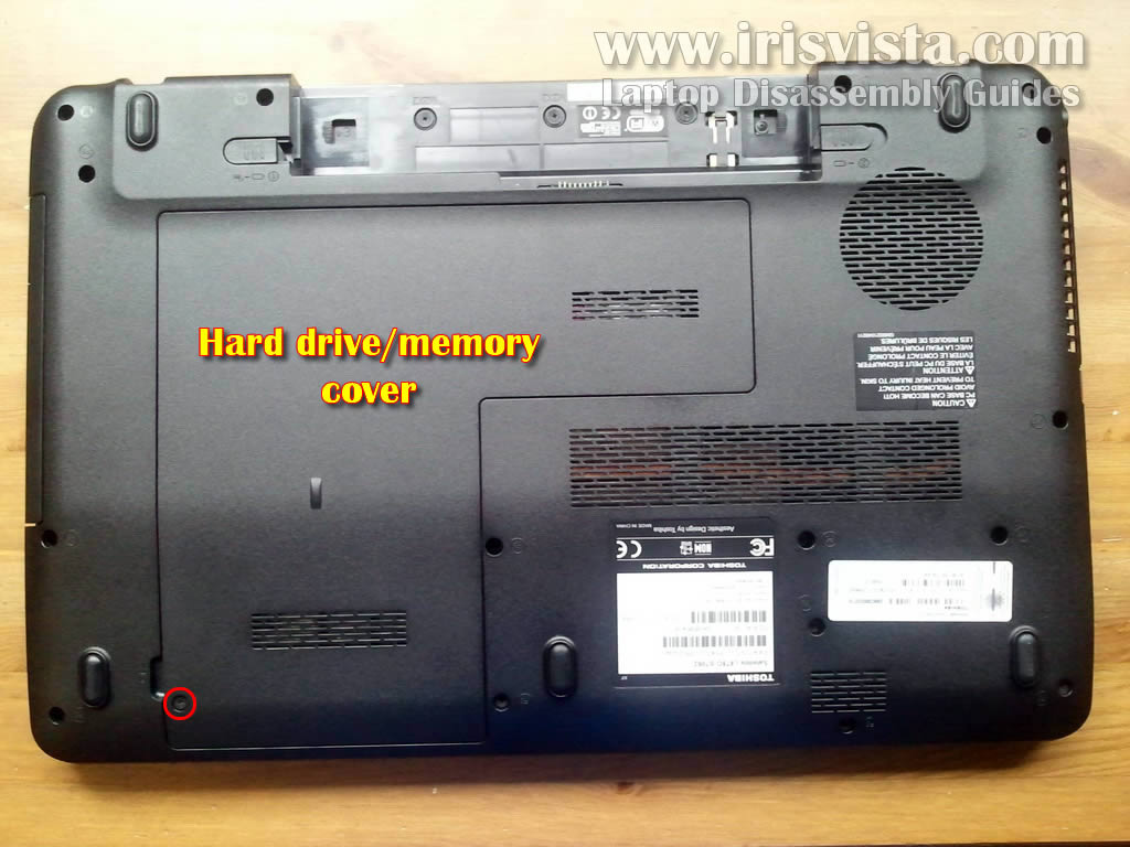
STEP 1
When you start dismantling the laptop you have to make sure it's turned off and battery removed.
Remove one screw securing the hard drive and memory cover.
Lift up and remove the cover.
|
| |
|
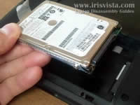 |
STEP 2
There are no screws securing the hard drive.
Simply slide the hard drive to the left and disconnect it from the motherboard.
Lift up and remove the hard drive.
|
| |
|
 |
STEP 3
Both memory modules located under the same cover.
Remove both memory modules if needed.
Toshiba Satellite L675D takes DDR3 PC3-8500 memory modules. |
| |
|
 |
STEP 4
Remove one screw securing the DVD drive.
Pull DVD drive from the laptop and remove it.
|
| |
|
 |
STEP 5
In the following seven steps I show how to remove the keyboard.
Lift up keyboard bezel with a sharp object. Continue removing the bezel with your fingers. |
| |
|
 |
STEP 6
Remove four screws securing the keyboard on the top. |
| |
|
 |
STEP 7
Lift up the keyboard and move it towards the LCD screen. |
| |
|
 |
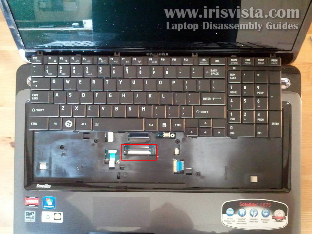
STEP 8
Now you can access cable connector located under the keyboard.
Before you remove the keyboard you'll have to unlock the connector and release the cable. |
| |
|
 |
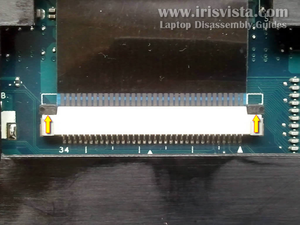
STEP 9
This picture shows keyboard connector in the locked position.
In order to unlock it move the brown locking tab about 1 millimeter towards the LCD screen.
Do not separate locking tab from the connector base.
|
| |
|
 |
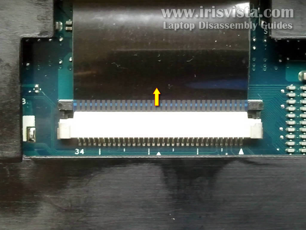
STEP 10
This picture shows keyboard connector in the unlocked position.
Now you can pull keyboard cable from the connector. |
| |
|
 |
STEP 11
Remove keyboard from the laptop.
Now you can replace the keyboard with a new one if needed. |
| |
|
 |
STEP 12
Remove all screws from the bottom of the laptop. |
| |
|
 |
STEP 13
Remove five screws securing the top cover assembly.
Disconnect touchpad cable from the motherboard.
|
| |
|
 |
STEP 14
There is no locking tab securing the touchpad cable.
Simply pull it from the connector. |
| |
|
 |
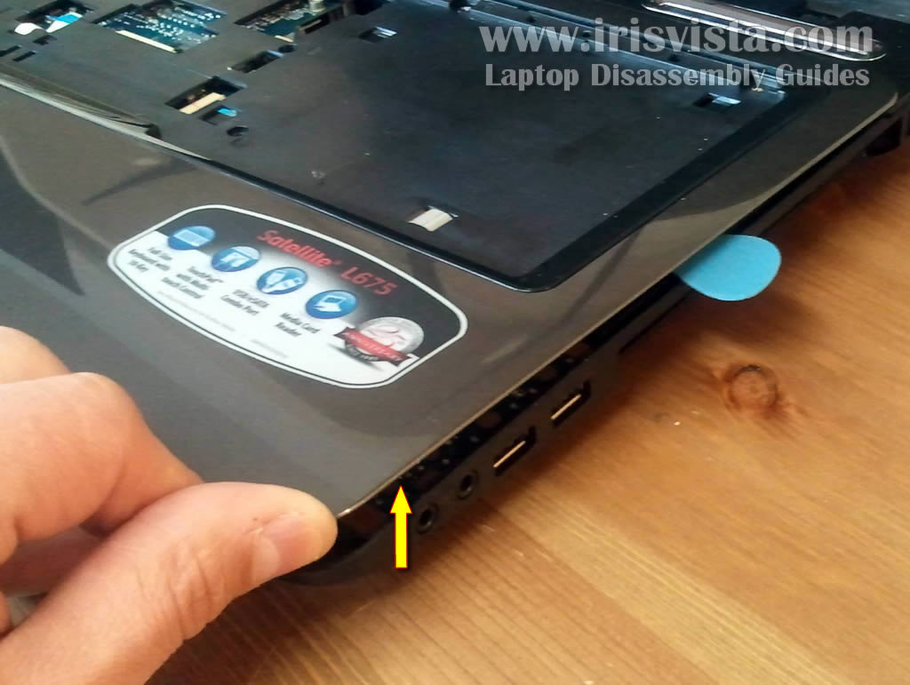
STEP 15
Start separating top cover assembly from the laptop base.
I'm using guitar pick as a case cracker. |
| |
|
 |
STEP 16
Lift up and remove top cover assembly. |
| |
|
 |
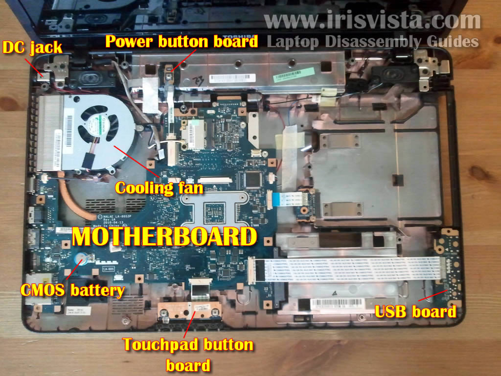
STEP 17
When top cover remove you'll get access to the following parts:
- DC jack
- Power button board
- Cooling fan
- CMOS battery
- USB board
- Touchpad button board
- and motherboard |
| |
|
 |
STEP 18
The cooling fan located in the top left corner.
In order to remove the fan you'll have to remove two screws and unplug fan cable from the motherboard. |
| |
|
 |
STEP 19
Lift up and remove cooling fan. |
| |
|
 |
STEP 20
The DC jack is not soldered to the motherboard.
It's attached to the power cable. |
| |
|
 |
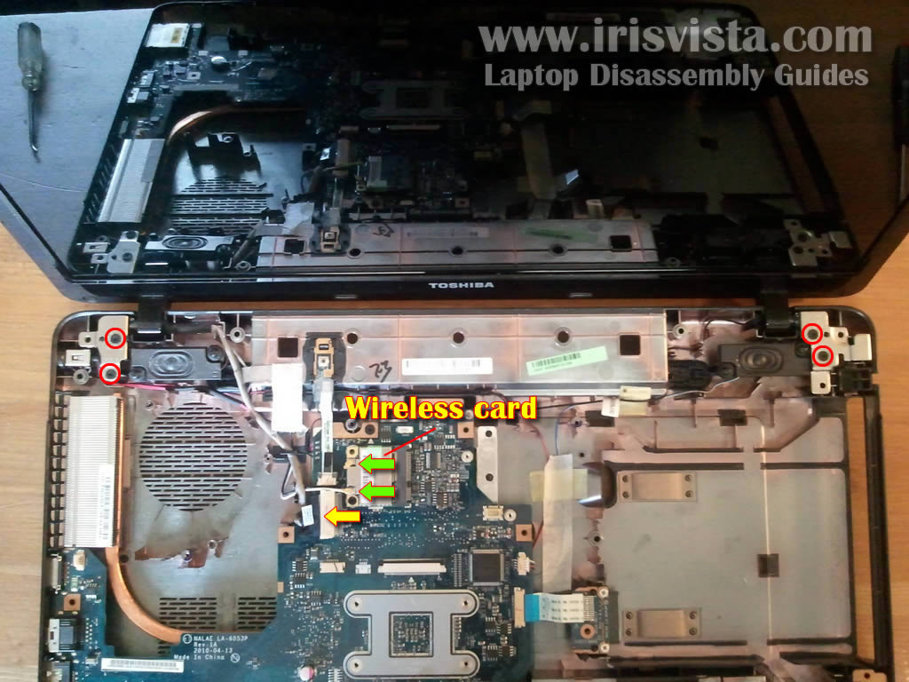
STEP 21
In order to remove the display panel you'll have to:
- Disconnect two wireless cables from the wireless card
- Disconnect video cable from the motherboard
- Remove four screws securing display hinges
After that you can lift up and remove the display cover.
The LCD screen removal steps should be similar to this laptop. |
| |
|
|
|