|
Toshiba Satellite M645, M645D, M640, M640D disassembly.
Also, check my next guide showing how to remove the screen. |
|
|
 |
STEP 1
Make sure the laptop is turned off.
Start disassembly with removing the battery.
|
| |
|
 |
STEP 2
Toshiba Satellite M645 laptop has two covers on the bottom. One for the hard drive and another one for memory modules and wireless card.
Remove two screws securing bottom covers. Lift up and remove both covers.
|
| |
|
 |
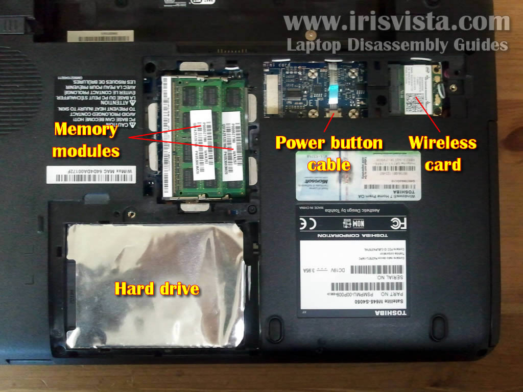
STEP 3
On the bottom of the laptop you can get access to the following components:
- hard drive.
- both memory modules.
- wireless card.
- power button membrane board connector.
Toshiba Satellite M645, M645D, M640, M640D laptops can take up to 8GB RAM maximum. You can install up to 4GB RAM module into each slot.
For the purpose of my disassembly it's not necessary to remove memory modules and wireless card.
I'll leave them connected to the motherboard and remove only the hard drive. |
| |
|
 |
STEP 4
Slide the hard drive assembly to the left to disconnect it from the motherboard.
Lift up and remove the hard drive assembly. As you see, the hard drive wrapped in the aluminum shielding.
My Toshiba Satellite M645 laptop had a regular 2.5" SATA hard drive installed.
This hard drive can be replaced with any other large capacity 2.5" SATA hard drive or SSD. |
| |
|
 |
STEP 5
Remove one screw securing the optical DVD drive.
Pull DVD drive to the right to disconnect it from the motherboard. Remove DVD drive from the laptop. |
| |
|
 |
STEP 6
Remove two screws securing the keyboard on the bottom of the laptop. |
| |
|
 |
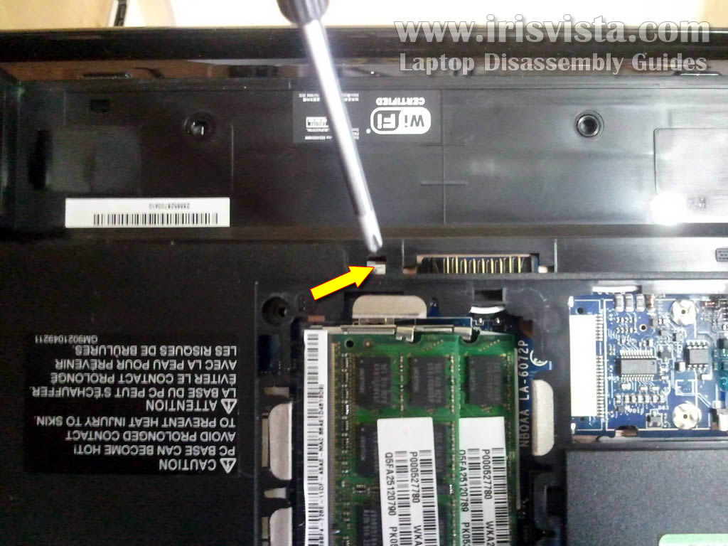
STEP 7
Here's how to remove the keyboard.
This laptop has a small opening on the bottom, on the left side from the battery connector. You can see the bottom side of the keyboard though this opening.
Carefully push on the keyboard with a screwdriver. Do not apply too much pressure. You'll have to push the keyboard just enough to lift it up a little bit on the other side. |
| |
|
 |
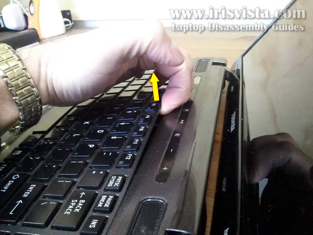
STEP 8
While pushing on the bottom, insert your fingers between the keyboard and laptop base and start removing the keyboard.
There are small plastic latches securing the keyboard. You'll have to apply some pressure to separate the keyboard from the base. |
| |
|
 |
STEP 9
Lift up the upper side of the keyboard and move the keyboard towards the screen.
Be careful, the keyboard still attached to the motherboard. |
| |
|
 |
STEP 10
Now you can access the keyboard cable connector.
It's necessary to unlock the connector and release the cable before removing the keyboard. |
| |
|
 |
STEP 12
On this picture the keyboard connector shown in the locked position.
Move the white locking tab about 1-2 millimeters towards the screen.
The locking tam MUST stay attached to the connector base. |
| |
|
 |
STEP 13
On this picture same connector shown in the unlocked position.
After the cable is released, you can pull it from the connector. |
| |
|
 |
STEP 14
Lift up and remove the keyboard.
|
| |
|
 |
STEP 15
Now I'll be taking apart the laptop base.
Remove all screws from the bottom of the laptop.
|
| |
|
 |
STEP 16
Remove four screws securing the top cover assembly.
Disconnect the following cables:
1. Left speaker cable.
2. Media control board
cable.
3.
Touchpad board cable.
4. Touchpad button board cable.
5. Right speaker cable. |
| |
|
 |
STEP 17
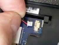
Both speaker cables are regular male-female type connectors.
Unplug male part from the female part by the connector edges. Do not pull by the wires. |
| |
|
 |
STEP 18
The medial control board connector and touchpad connectors do not have locks.
Simply pull cables from the connector by the blue tab. |
| |
|
 |
STEP 19
Start separating the top cover assembly from the laptop base. |
| |
|
 |
STEP 20
If the top cover doesn't separate, you can use a piece of soft plastic (I'm using a guitar pick).
Insert it between the top cover and laptop base and slowly move along the side. |
| |
|
 |
STEP 21
Lift up and remove the top cover assembly. |
| |
|
 |
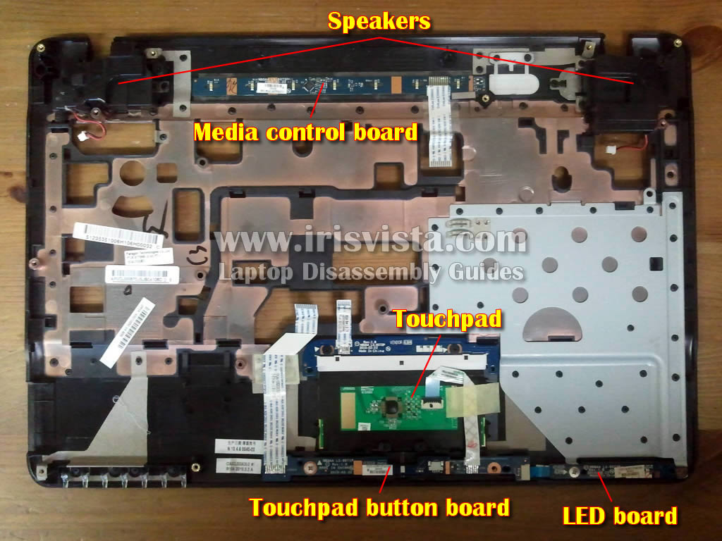
STEP 22
On the other side of the top cover assembly you can access the following components:
- both speakers.
- media control board.
- touchpad.
- touchpad button board.
- LED board (lights up Toshiba logo on the front). |
| |
|
 |
STEP 23
After you remove the top cover, you can access the following internal laptop components:
- power button membrane board.
- DC power jack (the DC jack is attached to the harness which can be unplugged from the motherboard without soldering anything).
- cooling fan (it's mounted on the bottom side of the motherboard. It means the motherboard has to be removed in order to replace the fan.).
- CMOS battery (soldered to the motherboard). |
| |
|
|
|