 |
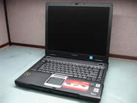
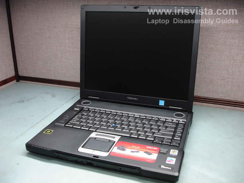
Toshiba Tecra S3 disassembly.
This guide has four pages:
PAGE 1. Removing memory, hard drive, DVD drive and wireless card.
PAGE 2. Removing keyboard and touchpad.
PAGE 3. Removing top cover, cooling fan assembly and video card.
PAGE 4. Removing notebook motherboard. |
|
|
 |
STEP 1
Open both battery locks and pull the battery from the notebook.
|
| |
|
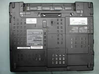 |
STEP 2
Remove the hard drive cover, the wireless card cover and the memory module cover. Each cover is secured by one screw.
|
| |
|
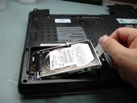 |
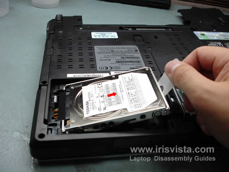
STEP 3
Lift up the right side of the hard drive by the plastic strip attached to the hard drive holder.
Pull the hard drive to unplug it from the connector.
If you are replacing the hard drive, you will have to transfer the
holder to a new drive.
|
| |
|
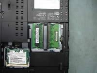 |
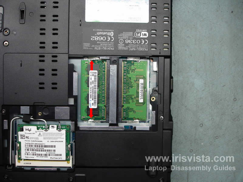
STEP 4
Both memory modules (memory slots) are accessible from the bottom of the notebook.
To remove the memory module spread the latches first and when the memory module pops up, pull it from the slot. Repeat it with the second memory module. |
| |
|
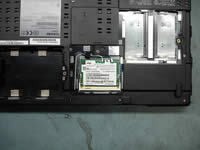 |
STEP 5
Before you remove the wireless card, you have to disconnect the wireless antenna wires from the card. Each wireless antenna has a small round connector that snaps on the wireless card. You can unsnap the connectors with your fingers.
After the antenna cables are disconnected from the wireless card, spread the slot latches and when the card pops up pull it from the slot.
|
| |
|
 |
STEP 6
Release wireless antenna cables and ferrite ring. |
| |
|
 |
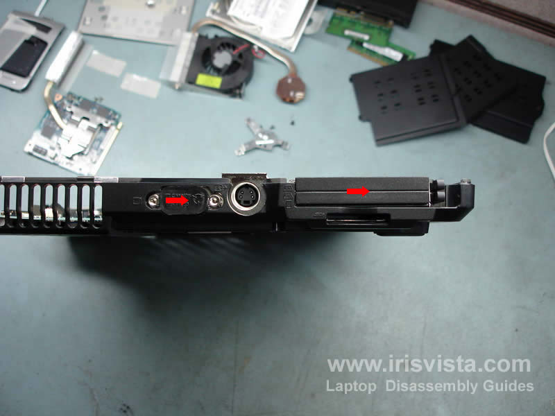
STEP 7
Remove the DVD drive from the laptop. Release the lock and pull the drive from the notebook. |
| |
|
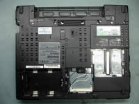 |
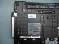
STEP 8
Here's some fun for you. Remove all screws marked with a red circle.
There is one screw that is hidden under the seal. Remove the seal and then remove the screw.
You might notice that screws have different length and it's marked on the laptop base.
F8-8milimeter screw, F16-16millimenter screw. |
| |
|
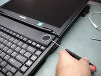 |
STEP 9
Now it's time to turn the notebook over and remove the keyboard bezel.
You can remove the bezel with a flathead screwdriver. Insert the screwdriver between the bezel and the laptop base and carefully work it up. Continue removing the keyboard bezel with your fingers. |
| |
|
 |
STEP 10
Remove the keyboard bezel. |
| |
|
 |
STEP 11
Remove the keyboard screws and press on the keyboard lock.
Lift up the keyboard and flip it over. Be careful, the keyboard cable is still attached to the motherboard. |
| |
|
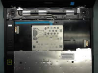 |
STEP 12
Remove one screw that secures a metal plate over the keyboard connector. |
| |
|
 |
STEP 13
After the screw is removed, slide the metal plate up and remove it.
|
| |
|
 |
STEP 14
Turn the keyboard over again, so you can easily access the connector on the motherboard.
Unlock the connector by lifting the lock 2-3mm up.
After the connector is opened, pull the cable and remove the keyboard. |
| |
|
 |
STEP 15
The power switch board connects to the motherboard via a flat (blue) cable and the cable is secured with a sticky tape.
Remove the tape. Unlock the connector and pull the cable.
Remove one screw securing the power switch board cover.
|
| |
|
 |
STEP 16
Removing the switch cover is a little bit tricky.
You have to lift up one side with a small screwdriver and at the same time slide the cover to the right.
After that you can lift it up and remove. |
| |
|
 |
STEP 17
Remove one screw securing the power switch board and remove the board. |
| |
|
 |
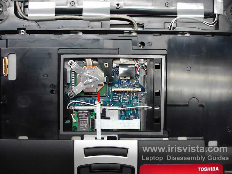
STEP 18
Carefully open the touchpad cable connector on the motherboard and pull the cable. You have to be very gentle because it's a small connector and could be easily damaged. |
| |
|
 |
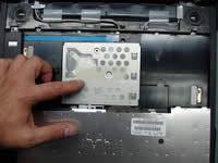
STEP 19
Lift up the touchpad assembly as it shown on the photo and remove it from the notebook. |
| |
|
 |
STEP 20
Peel off Mylar cover and disconnect the cable that comes from the finger scan device.
Unlock the connector before you pull the cable. |
| |
|
 |
STEP 21
It's not necessary to the Bluetooth card at this point. Just unplug the Bluetooth cable from the motherboard and leave the card attached to the top cover.
Unplug the speaker cable from the motherboard.
Remove one screw securing the top cover assembly. |
| |
|
 |
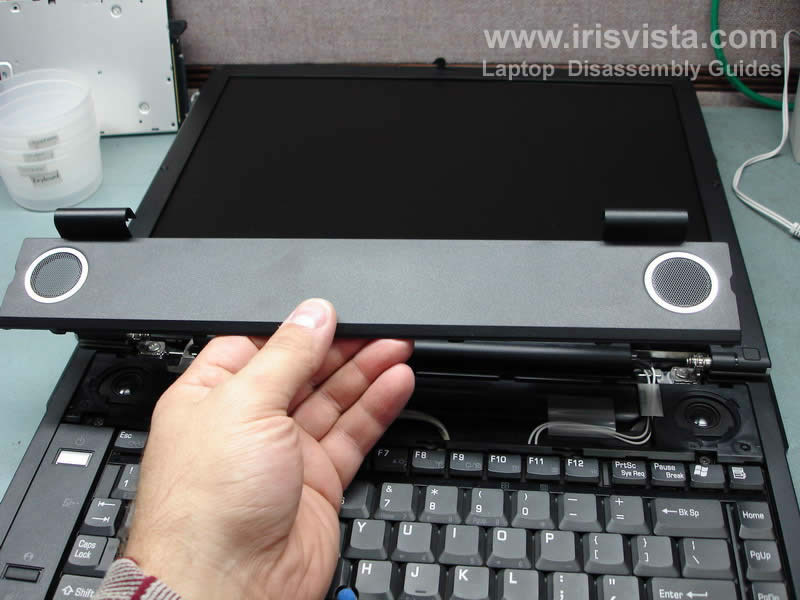
STEP 22
Lift up the top cover with display assembly starting from the back.
By the way, in the next guide I explain how to remove the screen. |
| |
|
 |
STEP 23
Be careful. Before you remove the top cover assembly, you'll have to pull the wireless card antennas through the opening in the motherboard.
After the wireless antennas are released, you can remove the top cover and display assembly.
|
| |
|
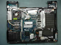 |
STEP 24
Here's a view on the system board without the top cover. |
| |
|
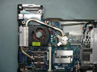 |
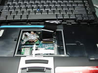
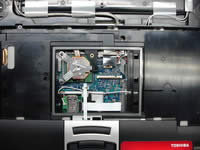
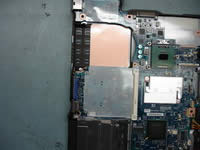
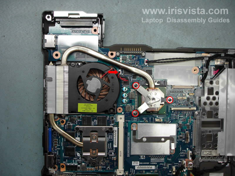
STEP 25
Now we are going to remove the processor cooling module.
Remove three screws from a metal plate that keeps the heatsink in place. Remove the plate.
Unplug the fan cable from the connector on the motherboard. |
| |
|
 |
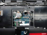
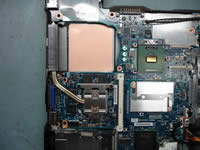
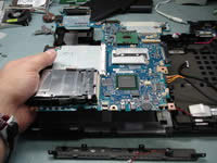
STEP 26
Remove the cooling module. Clean up the old thermal grease from the processor and from the heatsink. You'll have to apply new thermal grease when you assemble it back. |
| |
|
 |
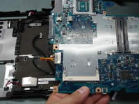
STEP 27
This photo shows the notebook in two halves. On the left side - the top cover/display assembly. On the right side - the notebook base with all boars inside. |
| |
|
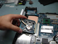 |
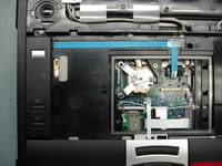
STEP 28
Remove two screws from the video board and when the board pops up, pull it from the video slot. Remove the video board. |
| |
|
 |
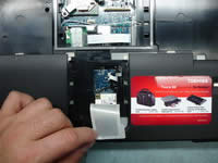
STEP 29
If you are replacing the motherboard, do not forget to remove the VGA port cap and the dummy PC card and transfer them to the new board. |
| |
|
 |
STEP 30
Disconnect the USB board cable from the motherboard and put the cable aside.
Disconnect the RTC battery cable and the internal speaker cable.
Remove two screws from the modem card, pull the modem up to disconnect it from the motherboard and unplug the modem cable. |
| |
|
 |
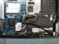
STEP 31
Unplug four cables markee with a red arrow.
Remove one screw securing the cable holder and put the holder aside. |
| |
|
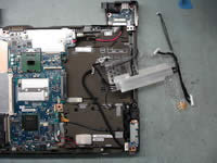 |
STEP 32
Disconnect the power jack cable from the motherboard.
The cable holder looks like an octopus, isn't it? :) |
| |
|
 |
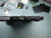
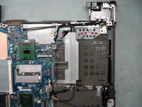
STEP 33
Remove two screws securing the front face plate. |
| |
|
 |
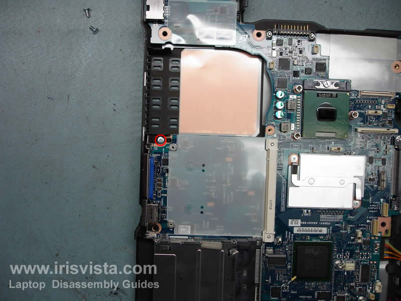
STEP 34
Remove one screw securing the motherboard. |
| |
|
 |
STEP 35
Carefully lift up the motherboard from the notebook base. The SATA drive cable is still attached to it. Turn over the motherboard so you can disconnect the hard drive cable. |
| |
|
 |
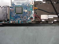
STEP 36
Remove the tape and unplug the hard drive cable. |
| |
|
 |
STEP 37
At this last step remove the processor.
Turn the screw-lock located on the socket into "Open" position and carefully lift up the processor from the motherboard. |
| |
|
|
|


