|
Toshiba Satellite P205, P200 disassembly. |
|
|
 |
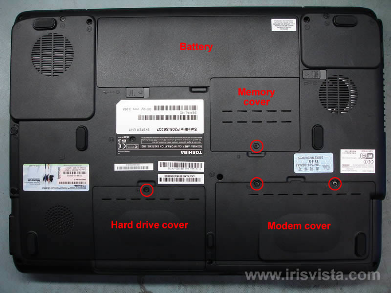
STEP 1
Remove the battery.
Remove memory cover, hard drive cover and modem cover.
Each cover is secured by one screw. |
| |
|
 |
STEP 2
Slide the hard drive to the left side to disconnect it from the motherboard.
Carefully lift up the hard dive and remove it from the laptop.
Remove both memory modules.
|
| |
|
 |
STEP 3
Remove both screws securing the modem card.
Carefully lift up the modem. The modem is connected to the motherboard. This connection is located under the modem so you cannot see it.
Unplug the modem cable. |
| |
|
 |
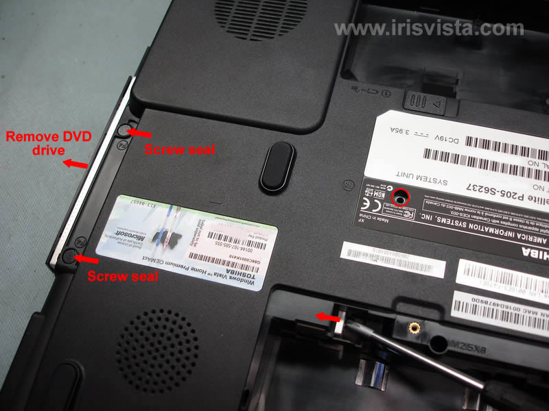
STEP 4
Remove one screw securing the DVD drive to the laptop case.
Remove two screw seals.
Push the DVD drive with a screwdriver and remove it from the notebook. |
| |
|
 |
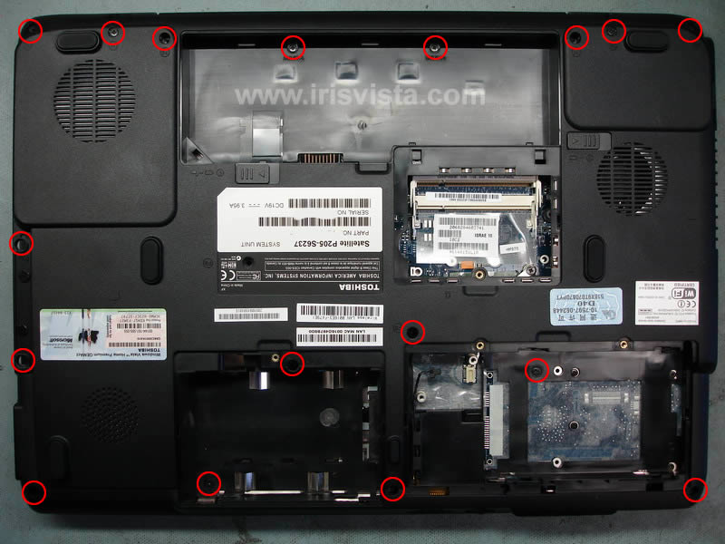
STEP 5
Remove all screws marked with red circle.
In the previous step you removed two screw seals. There are two screws located under the seals and you can access these screws only after the DVD drive is removed. |
| |
|
 |
STEP 6
Remove two screws from the back side of the notebook.
These screws securing hinges. |
| |
|
 |
STEP 7
Turn the laptop over and start removing the keyboard bezel.
You can use a guitar pick.
|
| |
|
 |
STEP 8
After all latches are released you can remove the keyboard bezel. |
| |
|
 |
STEP 9
After the keyboard bezel is removed, you get access to four keyboard screws.
Remove all four screws. |
| |
|
 |
STEP 10
Carefully lift up the keyboard so you can access the keyboard cable connected to the motherboard.
Unlock this connector and remove the keyboard cable. |
| |
|
 |
STEP 11
In order to split the notebook case, you'll have to remove all marked screws located under the keyboard. |
| |
|
 |
STEP 12
Unplug both wireless card antenna cables.
Remove two screw securing the wireless card and remove the card. |
| |
|
 |
STEP 13
Disconnect the switch board cable from the motherboard.
Before you pull the cable, unlock the connector. |
| |
|
 |
STEP 14
Start separating the speaker cover from the notebook.
Again, you can use the same guitar pick. |
| |
|
 |
STEP 15
After all latches are released, lift up the back side of the speaker cover. |
| |
|
 |
STEP 16
Remove the speaker cover. |
| |
|
 |
STEP 17
Unplug the video cable, the touchpad cable and other small connectors.
Remove cables from their routs on the top cover. |
| |
|
 |
STEP 18
Remove two screws securing the display assembly hinges. |
| |
|
 |
STEP 19
Lift up and remove the display assembly.
In my next guide you will find screen removal instructions. |
| |
|
 |
STEP 20
Start separating the top cover assembly from the notebook base by moving the guitar pick alone the side. |
| |
|
 |
STEP 21
Remove the top cover assembly. |
| |
|
 |
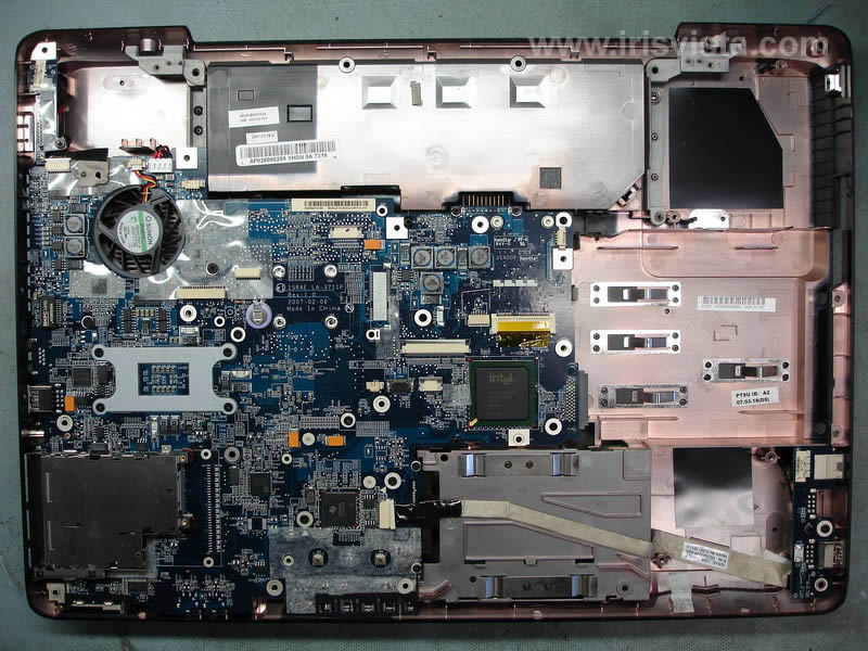
STEP 22
Now you can access the motherboard. |
| |
|
 |
STEP 23
In order to remove the motherboard, you'll have to remove the VGA connector board first.
Remove one screw and unplug the cable from the motherboard. |
| |
|
 |
STEP 24
Remove two hex studs from the VGA port on the left side of the notebook. |
| |
|
 |
STEP 25
Remove the VGA connector board. |
| |
|
 |
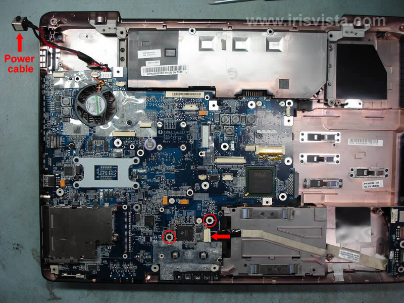
STEP 26
Unplug the USB board cable.
Remove two screws securing the motherboard.
Release the power cable. |
| |
|
 |
STEP 27
Start remving the motherboard from the notebook case. |
| |
|
 |
STEP 28
Lift up and remove the motherboard. |
| |
|
 |
STEP 29
Unplug the cooling fan cable and turn the motherboard over. |
| |
|
 |
STEP 30
Now you can remove six screws from the heatsink, remove the heatsink and access the CPU.
Remove the cooling fan.
When you assembly everything back together, do not forget to apply thermal grease on the CPU and northbridge.
You have to use special grease for the northbridge. Here's the part number for this grease: K000051370
For CPU you can use the following grease: X-23-7762-01
|
| |
|
|
|