|
Toshiba Satellite A665, A665D, A660, A660D disassembly. |
|
|
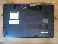 |
STEP 1
Before you start, make sure the laptop is turned off (not hibernated or in sleep mode) and battery removed.
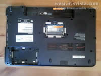
Loosen/remove two screws securing the hard drive and memory covers.
Lift up and remove both covers.
|
| |
|
 |
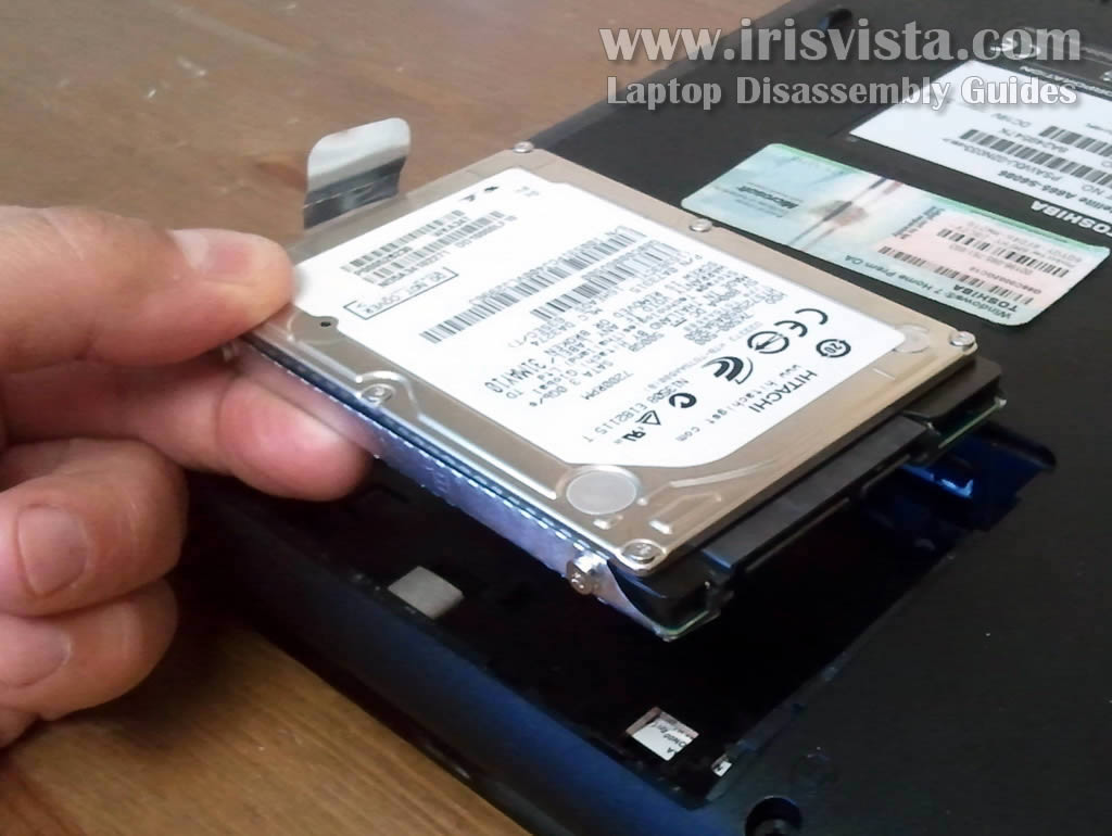
STEP 2
Slide the hard drive to the left to disconnect it from the motherboard.
Lift up and remove the hard drive.
Note: in my Toshiba Satellite A665 laptop I had a regular 500GB 2.5" SATA hard drive installed. You can upgrade it to any larger 2.5" SATA hard drive or SSD.
|
| |
|
 |
STEP 3
Both memory slots/modules can be accessed on the bottom of the laptop.
Remove both memory modules.
This laptop uses DDR3-8500 (1066MHz) memory modules. |
| |
|
 |
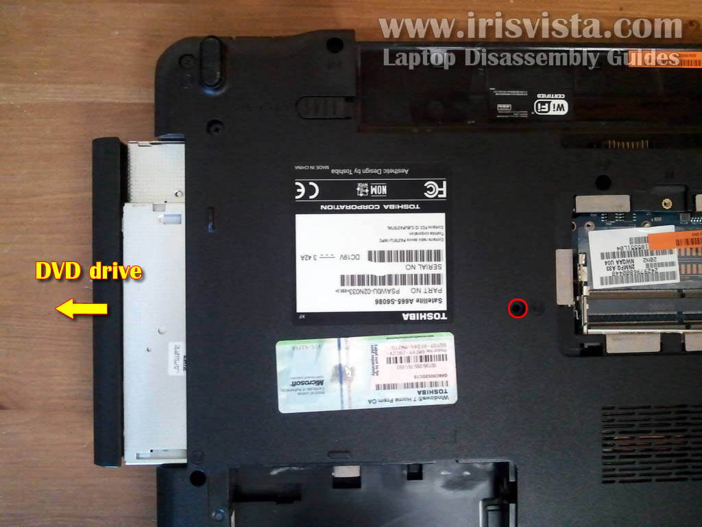
STEP 4
Remove one screw securing the DVD drive.
Pull DVD drive from the laptop and remove it.
|
| |
|
 |
STEP 5
The following seven steps explain how to remove the keyboard. If you just replacing the keyboard it's not necessary to go though all previous steps.
Remove three screws securing the keyboard on the bottom of the laptop. |
| |
|
 |
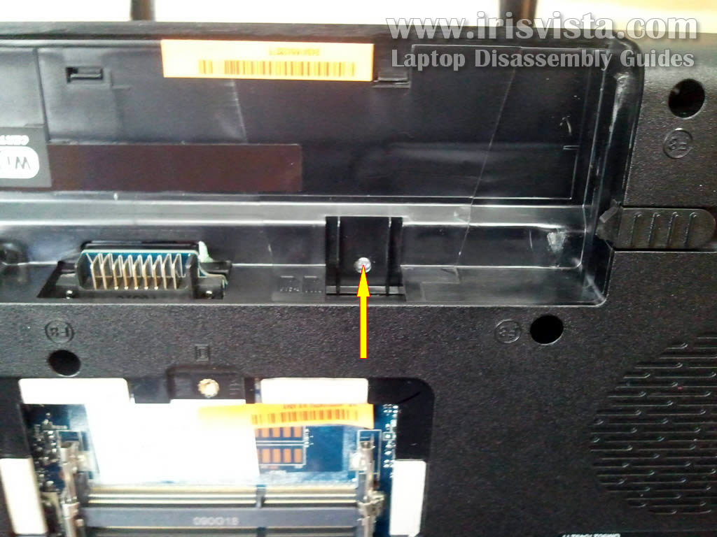
STEP 6
In Satellite A665/A665D laptop the keyboard seated very tightly.
You'll find a hole in the battery compartment.
Push on the keyboard through this hole with a not very sharp object.
At the same time grab the keyboard with your fingers on the other side of the laptop.
|
| |
|
 |
STEP 7
Lift up the keyboard. |
| |
|
 |
STEP 8
Move the keyboard towards the LCD screen so you can access the cable connector underneath.
You must unlock the connector and release keyboard cable before removing the keyboard. |
| |
|
 |
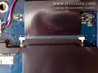
STEP 9
On this picture the keyboard connector shown in the locked position.
The connector has two parts: base (brown) which is soldered to the motherboard and locking tab (moving part).
Using your finger nails move the locking tab about 1 millimeter towards the LCD screen.
The locking tab must stay attached to the connector base. Do not move it too far.
|
| |
|
 |
STEP 10
On this picture the connector is shown in the unlocked position.
Now you can pull the cable from the connector. |
| |
|
 |
STEP 11
Remove the keyboard.
You can replace the keyboard with a new keyboard if needed. |
| |
|
 |
STEP 12
In the following six steps I explain how to remove the top cover assembly.
Remove all screws from the bottom of the laptop.
|
| |
|
 |
STEP 13
Remove two screws securing the top cover assembly.
Disconnect (from top to bottom): media board cable, speaker cable, touchpad cable. |
| |
|
 |
STEP 14
You simply pull the touch pad cable and media board cable from the connector. There is no locking tab. |
| |
|
 |
STEP 15
Carefully unplug the speaker cable.
Do not pull by the wires. Unplug the connector using your finger nails. |
| |
|
 |
STEP 16
Start removing the top cover assembly. |
| |
|
 |
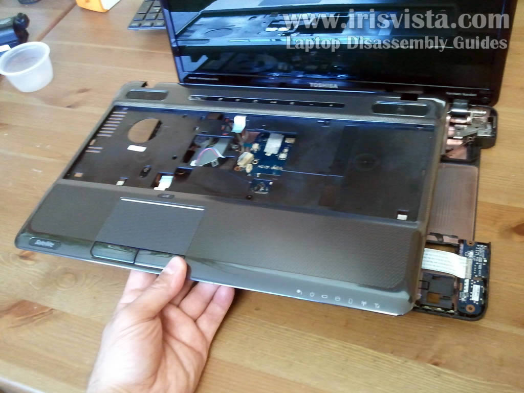
STEP 17
The top cover assembly removed. |
| |
|
 |
STEP 18
This picture shows the laptop without top cover assembly.
In the next two steps we'll remove the cooling fan which is located in the top left corner of the laptop. |
| |
|
 |
STEP 19
Remove two screws securing the cooling fan.
Disconnect cooling fan cable from the motherboard.
|
| |
|
 |
STEP 20
Remove and lift up the cooling fan.
Now you can clean up the heat sink or replace the cooling fan with a new cooling fan if needed. |
| |
|
 |
STEP 21
Disconnect two antenna cables from the wireless card.
Unplug video cable from the motherboard. |
| |
|
 |
STEP 22
Remove six screws securing display hinges to the laptop base.
Each hinge secured by three screws.
|
| |
|
 |
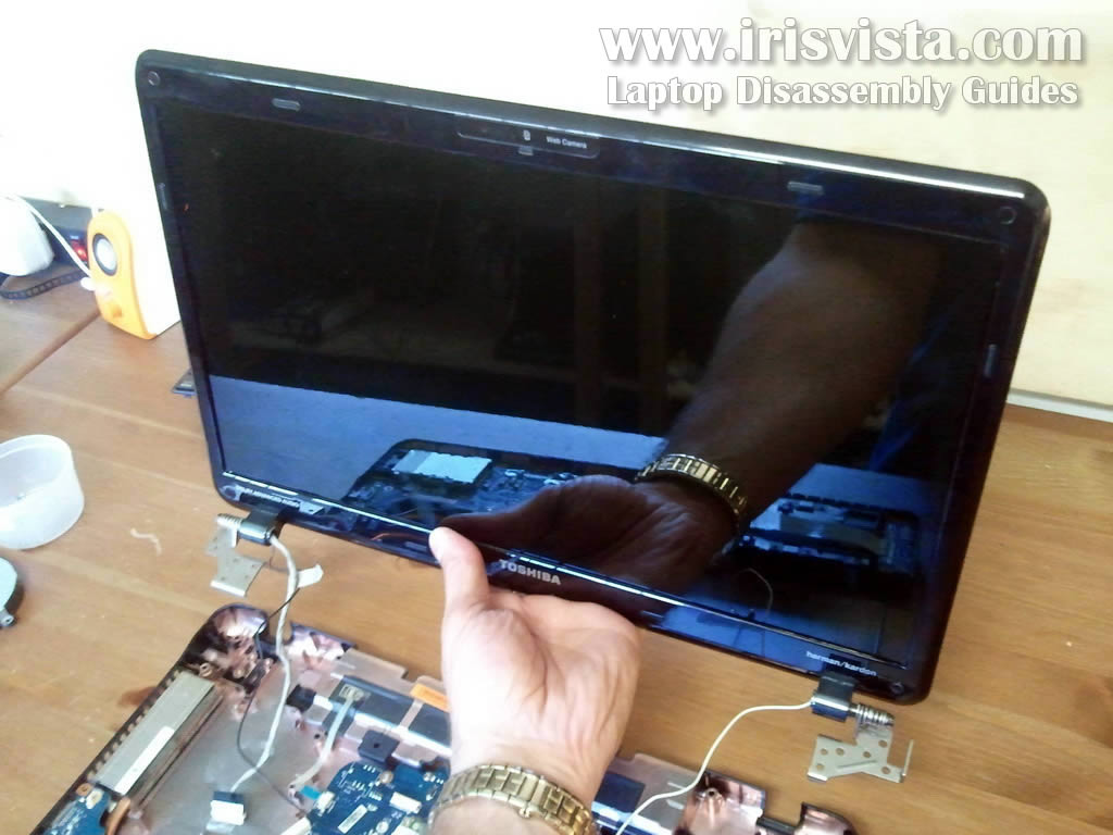
STEP 23
Lift up and remove the display assembly.
In one of the next guides I explain how to remove and replace LCD screen.
|
| |
|
 |
STEP 24
Remove one screw securing the motherboard.
Disconnect following cables (from top to bottom):
- power button cable.
- USB board cable.
- LED board cable.
Lift up DC jack from the laptop base and unroute the cable. |
| |
|
 |
STEP 25
Carefully lift up the right side of the motherboard.
|
| |
|
 |
STEP 26
Remove motherboard from the laptop. |
| |
|
 |
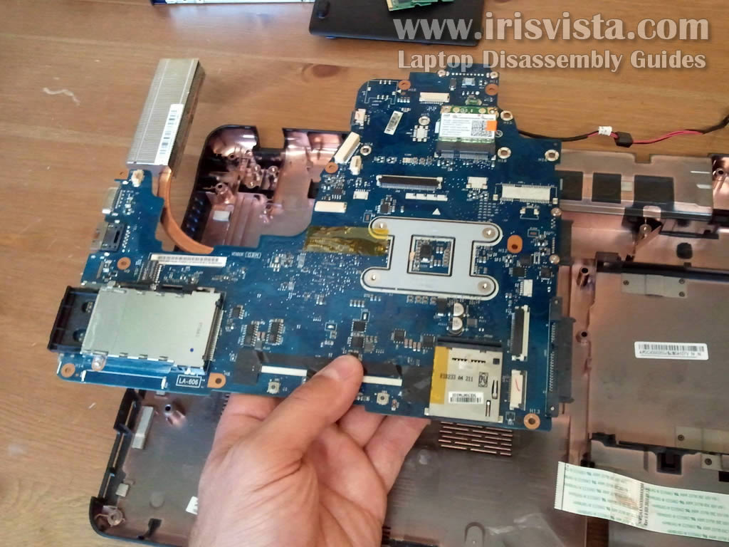
STEP 27
On this picture you can see the bottom side of the motherboard.
By the way, the CMOS battery is soldered to the motherboard and cannot be easily removed. It has to be desoldered. |
| |
|
|
|